4.5 Structure of the control electronics
The control electronic of the Connexx has a main board (with microprocessor chip).
All the basic functions of the equipment are controlled by this board.
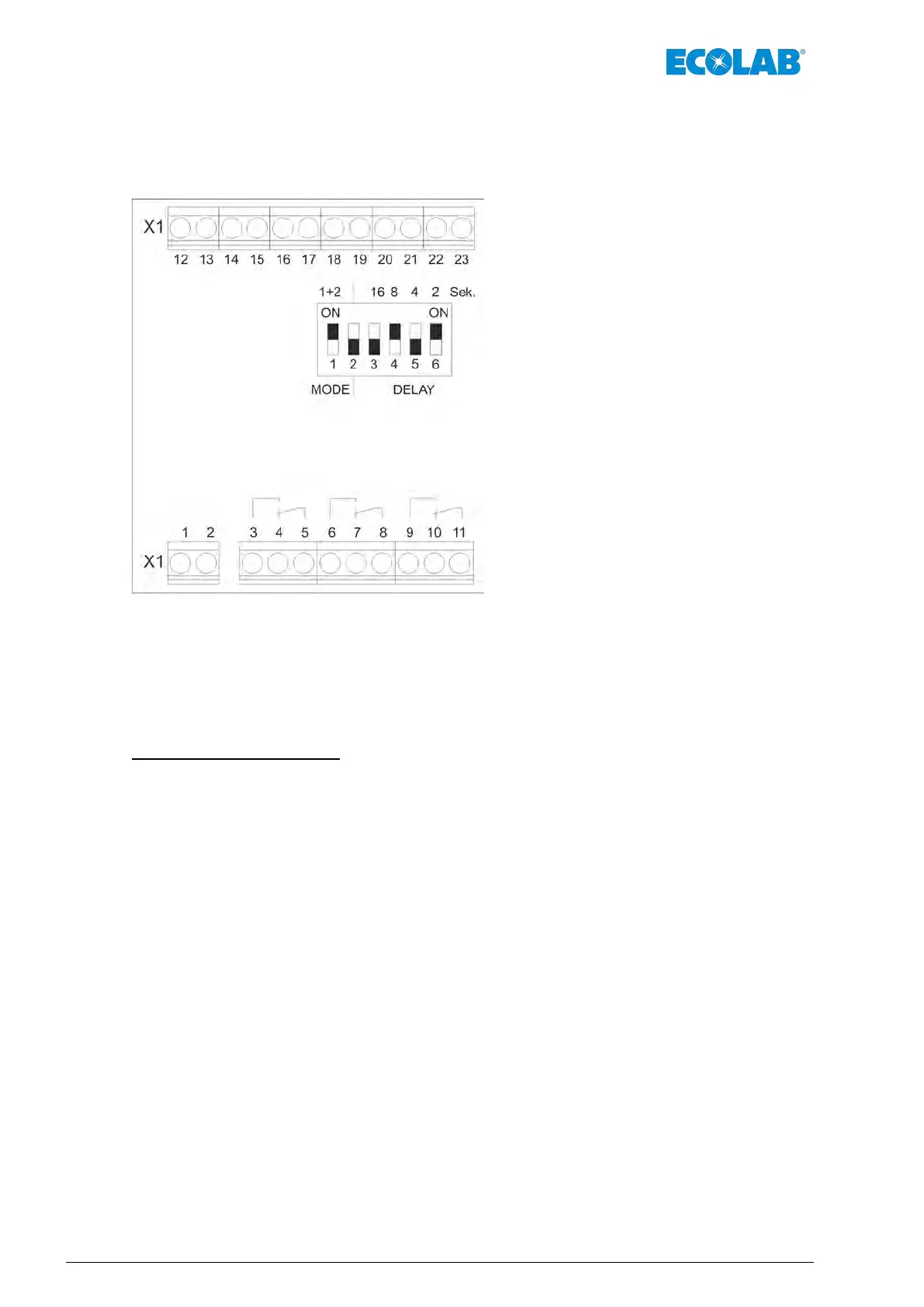
Fig. 10: Main board
X1 (12, 13) Lifting vessel
X1 (14, 15) Drum 1
X1 (16, 17) Drum 2
X1 (18, 19) Floater switch
X1 (20, 21) Enable externally
X1 (22, 23) Buzzer
X1 (1, 2) 24 V, AC Power
X1 (3, 4, 5) Alarm
X1 (6, 7, 8) Empty signal (LL1/ LL2)
X1 (9, 10, 11) Pump Enable
The main board contains:
n Relay output for empty signal of container 1 & 2 (LL1/2) (potential-free contact)
n Relay output for Pump Enable (potential-free contact)
n Relay output for collective fault signal (ALARM) (potential-freee contact)
n Relay output for solenoid valve at lifting vessel 24 V
, DC
n Relay outputs for two pilot valves (only in case of container switch-over) 24 V, DC
n Relay output for internal buzzer 24 V
, DC
n Voltage supply 24 V, AC
n Inlet for external Enable signal (potential-free contact)
n Inlet for lifting vessel level switch (potential-free contact)
n 3 pushbuttons for acknowledging the signals LL1, LL2 and QUIT
Ä
Chapter 4.5.3 ‘Operation and Displays’ on page 26.
n 4 LED displays for ON LL1, LL2 and collective fault signal
Ä
Chapter 4.5.3 ‘Operation and Displays’ on page 26.
n DIL switch for setting with/without container switch-over as well as timer period
Ä
Chapter 4.5.4 ‘Adjusting elements’ on page 26
Functional description
22Rev. 1-06.2018
 Loading...