n Distance between equipment and product storage housing as less as possible
(length of the suction hose max. 3 m!)
For a better venting, the suction line should
always be designed upward in the direction of lifting vessel.
n If the metering point lies below the lifting vessel, a pressure control valve or metering
valve with corresponding opening pressure must be used, in order to avoid thedraining
of lifting vessel through the pump(s).
n In order that while dealing with the Click & Plug connection coupling or through
suspended
suction hoses, there are no high loads on the
Connexx System and the
coupling connection on the containers, it is recommended to mount a pull relief for the
suction hose.
n The installation site should be selected in such a way that the exhaust air line from the
injector can be run into a safe area. Very long suction lines can reduce the
suction power of the injector and necessitate an increase in the nominal diameter
(
Ä
Chapter 4.2.3 ‘Compressed air supply and exhaust air connection’ on page 18).
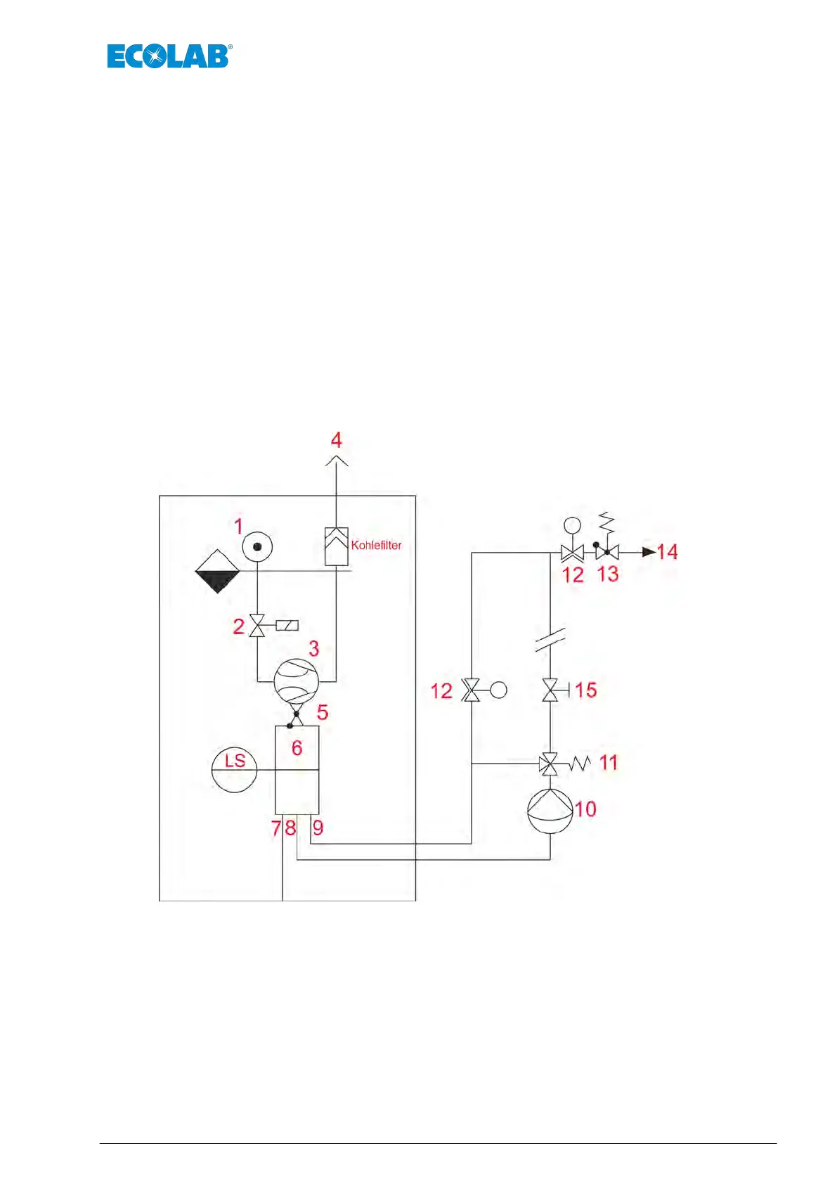
5.2 Protection when using a return connection
Fig. 14: Protection with return connection
1 Compressed air supply
2 Solenoid valve
3 Injector
4 Exhaust area
5 Non-return valve
6 Lifting vessel
7 Suction line container
8 Suction line pump
9 Return pipeline
10 Pump
11 Multi-function valve
12 Diaphragm valves (1 closed, if 2 open and vice versa)
13 Metering valve
14 Metering station
15 Diaphragm valve, hand-controlled
Assembly and Connection
29 Rev. 1-06.2018
 Loading...