CONFIGURATION OF KNOCK SENSORS PARAMETERS
EMU has the ability to work with common knock sensors and to take appropriate corrective actions
when knock is detected. Common correction strategies are to enrich the fuel dose and to retard
ignition timing. The EMU employs advanced knock processors designed for use with flat response
(wideband) knock sensors. Flat response knock sensors are able to capture much more
information than older style sensors, and advanced filtering and processing is performed by the
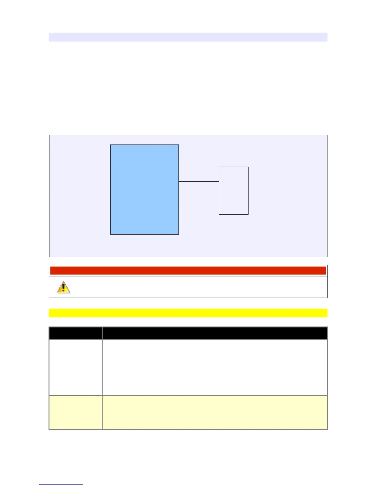
EMU in order to better detect knock. Connection for two-wire sensors is shown below. One-wire
sensors do not need a ground wire as the body of the sensor is grounded by mounting to the
engine block.
ATTENTION !
Knock sensors must be connected with shielded cables. Shielding must be
connected to ground on only one end.
Sensor parameters
PARAMETER DESCRIPTION
Knock
frequency
The engine knock characteristic frequency used to configure the band-pass
filter. This characteristic is different for every engine. It can be approximated
with the following equation:
Knock frequency (kHz) = 1800/(Pi * D)
Where D is cylinder diameter in millimeters
Gain
Knock sensor signal gain should be adjusted so that the Knock sensor value
parameter doesn't exceed 3V across the full RPM range during normal
combustion
Page 101
EMU
B2
KS
Knock sensor sample connection
B18
GND
Out