CONNECTING THE EMU DEVICE
When connecting the EMU device, special ATTENTION should be paid to the connection of
device’s grounds and their wiring in the car’s installation. Wrong connections can create loops, so
called Ground loops. Bad ground connections can cause many problems, such as noisy readings
from analogue sensors or problems with trigger errors. EMU device has several kinds of grounds.
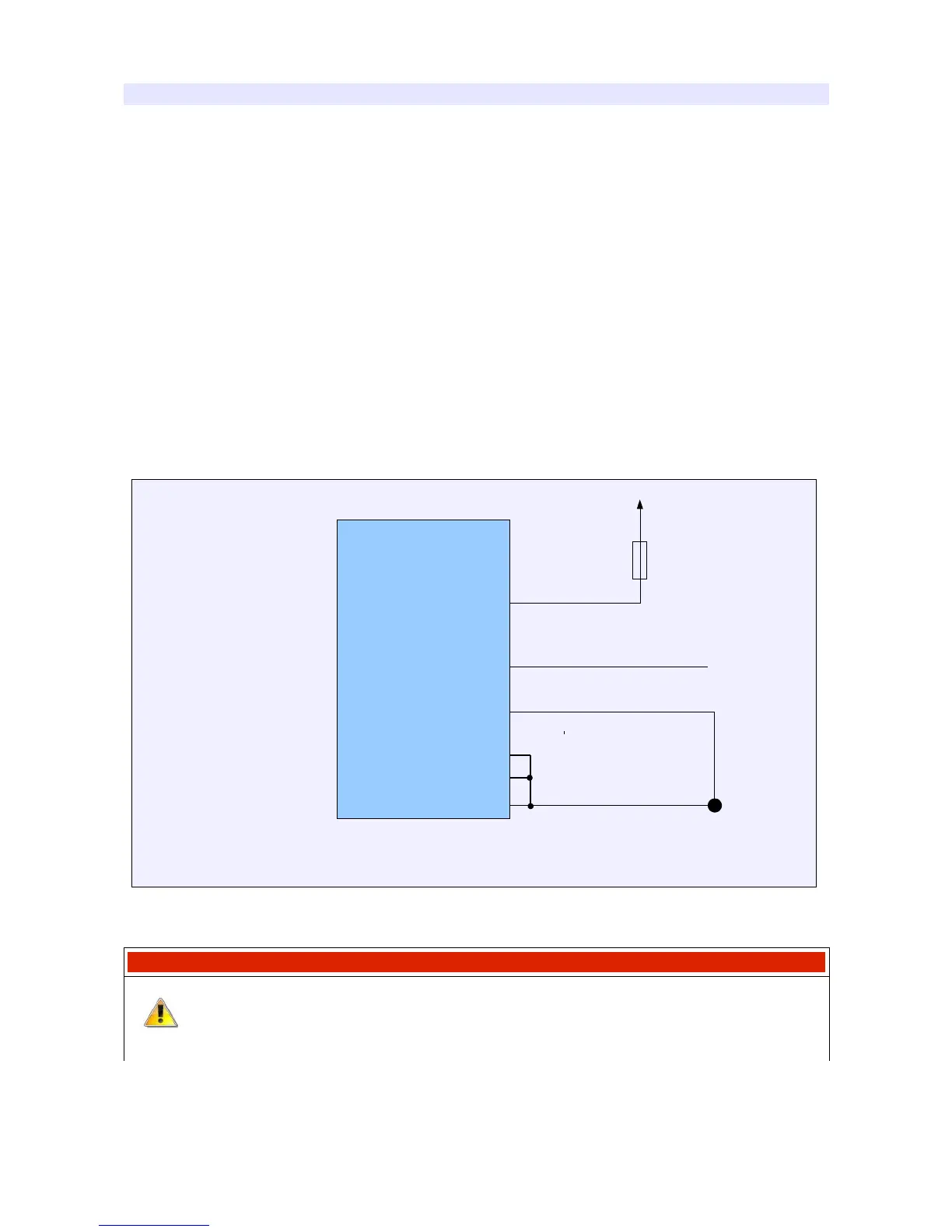
Device’s grounds (pin B17) is a ground used to power the device, analogue ground (pin B18) is the
ground point for analogue sensors, and power grounds (B24, G17 i G24) are used to supply power
outputs and ignition outputs. The perfect situation is when the device’s ground and power ground
are connected to one ground point on the block / engine’s head and are lead through separate
wires. Power grounds in case of using active coils should be connected using wires with the 1,5 –
2mm diameter. +12V power supply should be connected through the 3A fuse.
Below there is example of grounds’ connections to the device.
IMPORTANT !
Always use the fuses on the power lines!
Page 31
EMU
G18
B18
B17
G17
G24
B24
+12V
EMU device power scheme
3A
Ground point
on the engine
block
Sensors ground
Device ground
Power grounds