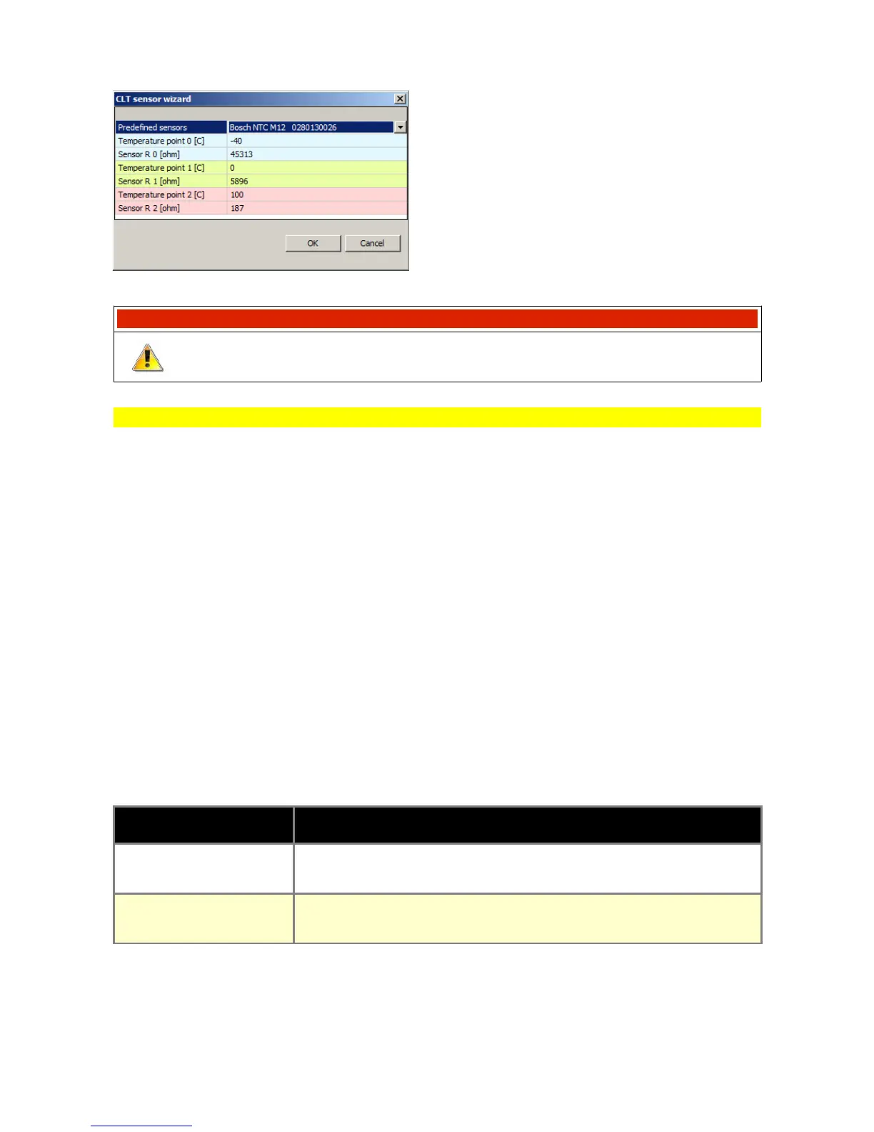
Predefined sensors – names of predefined
sensors. In case of choosing the „User defined”
sensor it is possible to add temperature values and
resistance of own sensor.
After selecting the sensor, you should press the OK
button, what will create the calibration table.
WARNING !
To permanently save a change in the device’s FLASH memory, you should
select Make Maps Permanent option (shortcut key F2).
CLT, IAT input
CLT, IAT input configuration window is used to define which inputs are used to read Intake Air
Temperature (IAT) and Coolant Temperature (CLT) sensors values. By default IAT and CLT
sensors should be connected to dedicated inputs (B21 and B4) which are equipped with internal
2.2K pull-up resistors connected to +5V.
When temperature sensors are shared with stock ECU, it is possible to connect them to
general purpose analog inputs to eliminate pull-up resistors influence on temperature
reading.
IAT sensor is essential for fuel calculation strategy. It's reading is used to calculate air density and
therefore air mass entering the cylinder.
CLT sensor is used to determine engine temperature and all fuel and ignition corrections related to
it. Also idle control is dependent on this sensor.
IAT and CLT calibration are defined in IAT sensor calibration and CLT sensor calibration 2D tables.
To create sensor calibrations, CLT Wizard and IAT Wizard can be used.
PARAMETER DESCRIPTION
CLT Input sensor
Use default input -CLT sensor connected to dedicated input (B4)
Analog input -CLT sensor connected to analog input
IAT Input sensor
Use default input - IAT sensor connected to dedicated input (B21)
Analog input - IAT sensor connected to analog input
Page 40