VSS and gearbox
Vehicle’s speed sensor is usually placed in the gearbox. It is used by factory systems, e.g.,
speedometer or the system supporting the steering wheel (e.g., electrical support system).
Vehicle’s speed can be also read from ABS sensors.
Ecumaster EMU device uses the VSS reading to regulate the boost pressure towards the vehicle’s
speed, controlling idle or the recognition of the currently selected gear.
To configure the VSS sensor, you should open the set of parameters VSS and gearbox.
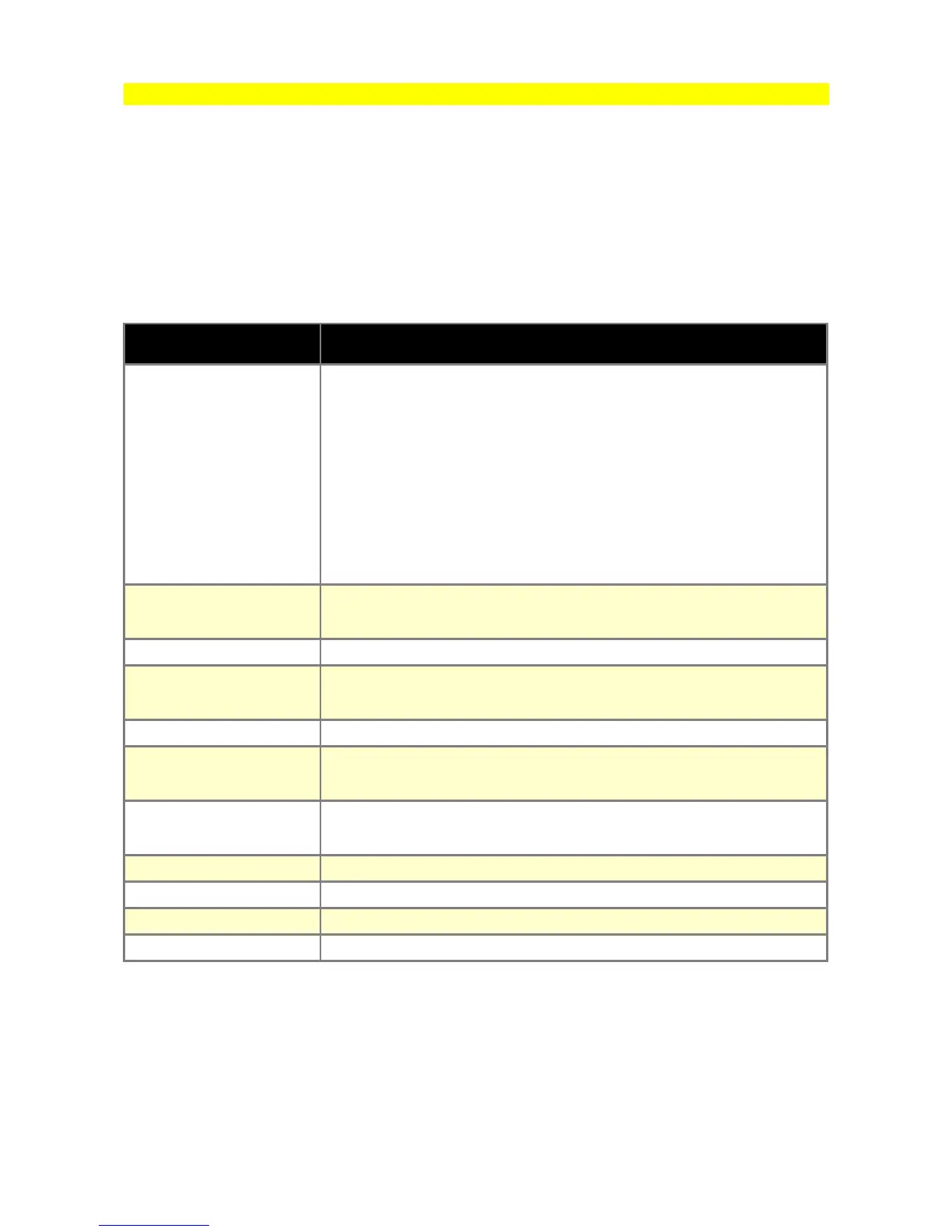
PARAMETER DESCRIPTION
Gear detection type
Calculated - current gear is determined on the basis of Vehicle Speed
/ Engine RPM ratio. Calculated ratios can be read from(VSS and
gears/ Gear ratio). For detection to work properly, ratios must be
entered in fields Gear x ratio
Gearbox sensor - current gear is determined by measuring voltage
from sensor located in gearbox. Sensor calibration can be found in
Gear sensor calibration table
CAN BUS - gear information is read from Can Bus signal
Sensor type
Type of sensor used to detect vehicle speed. VR or Hall sensor can
be selected
Trigger edge Edge of sensor signal used to calculate vehicle speed
Freq. divider
Speed sensor signal frequency divider is used in case of high
frequency signal
Enable pullup Activates 2k ohm pull-up resistor from signal input and +5V
Speed ratio
Frequency multiplier used to calculate km/h speed from VSS signal
frequency
Gear X ratio
Vehicle Speed / Engine RPM ratio for gear X. For calibration, value
can be checked in VSS and gears/ Gear ratio log.
Ratio tolerance Maximum allowed gear ratio deviation for gear to be determined
Gear sensor input Analog input used to connect gearbox gear sensor
CAN ID Can Bus frame ID containing information about current gear
CAN ID byte idx Number of byte in frame that contains information about current gear
Page 47