Ignition control
Idle ignition control function is used to control idle RPM by ignition angle modification. Advance of
ignition angle leads to increase of RPM, retardation lowers RPM. Ignition control regulates ignition
angle to achieve engine RPM defined in Idle target rpm table. Idle control state (active or not) and
current controller parameters can be checked in Log group idle.
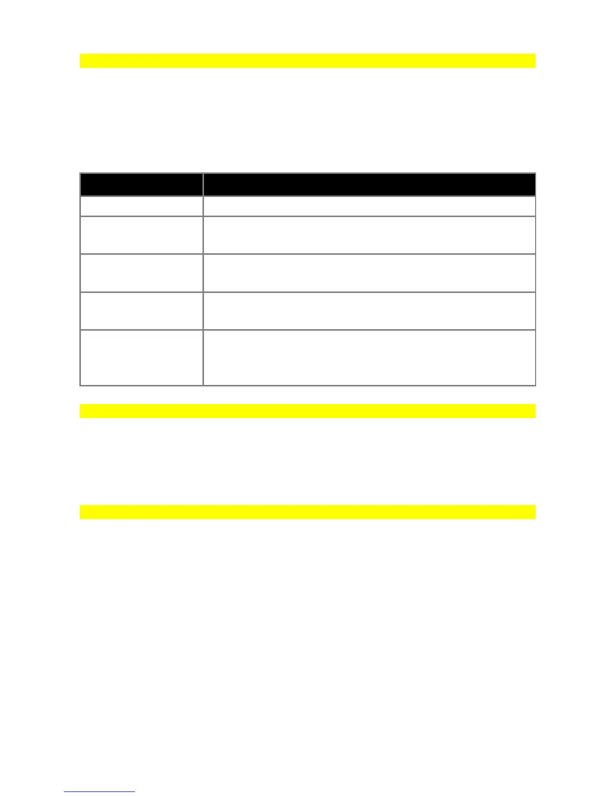
PARAMETER DESCRIPTION
Enable ignition control Activates idle control by ignition angle strategy
Use correction table
When checked, ignition angle is controlled by Idle ign. corr. table as a
function of RPM Error instead of being controlled with PID controller.
Max ignition advance
Defines maximum allowed ignition advance for PID controller. Not
used when Idle ign. corr. table is active.
Max ignition retard
Defines maximum allowed ignition retardation for PID controller. Not
used when Idle ign. corr. table is active.
Ignition angle change
rate
Defines how often ignition angle is changed. Value entered here is
number of engine cycles for one degree ignition angle change. Not
used when Idle ign. corr. table is active.
Idle target RPM
Idle target RPM table is used to define target engine idle RPM as a function of engine Coolant
Temperature (CLT). Table is active only when one of following idle strategies is active: PID control,
DC error correction or Ignition control.
Idle ref. table
Idle ref table is used to define base idle valve Duty Cycle as a function of engine Coolant
Temperature (CLT) when Idle Control is active. Values from table have different meaning in case of
different idle control devices. When PWM valve is used, DC of valve is defined. In case of stepper
motor, stepper position is calculated as DC * Stepper steps range. In case of Drive By Wire, idle
throttle opening angle is calculated as DC * DBW Idle range. When On/Off valve is used or idle
control is implemented with Ignition cut, Idle ref table is not used.
Page 99