PWM #1
The PWM #1 output is used to control an external solenoid with a predefined frequency and duty
cycle (DC) defined in 3D PWM table.
PARAMETER DESCRIPTION
Output Device output used for solenoid
Frequency The frequency of the PWM signal
Disable output if no RPM This option allows to disable PWM output during cranking
ATTENTION !
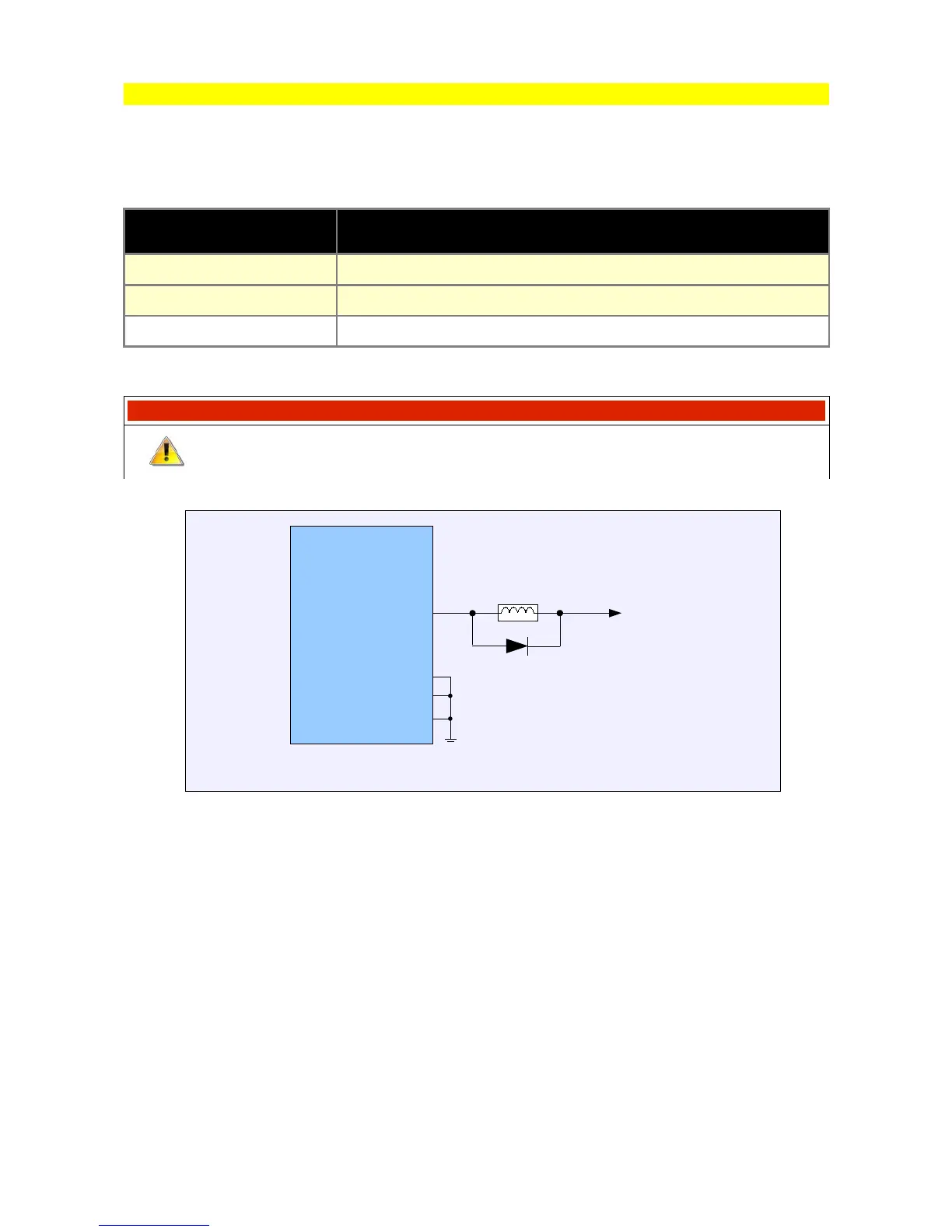
In the case of solenoid valves with high current consumption and high
frequency operation, use an external flyback diode.
Page 92
EMU
G12
G17
G24
B24
Example of the solenoid wiring diagram
+12V