ATTENTION !
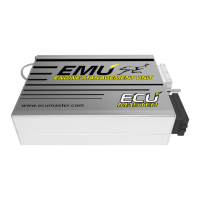
In case of VR sensors connecting the sensor with the device must be done with
the shielded cable, while the shield must be connected to the ground only at
one end!
ATTENTION !
In case of VR sensor the sensor’s polarity is important!
PARAMETER DESCRIPTION
Sensor type
Indicates the type of sensor connected to the Primary trigger input. For
Hall/Optical sensors option Enable pullup is required
Enable pullup
Enable 2K pullup to +5V on Primary trigger input. This function is used
in the case of Hall and Optical sensors that have open collector outputs
Trigger type
Supported Primary trigger decoders. More information about supported
decoders could be found further
Trigger edge
Trigger edge of input signal used for decoding trigger pattern. More
information about proper trigger selection can be found further
Number of cylinders
Number of engine cylinders. This determines the number of ignition
events which are always equal to number of cylinders
Num teeth (incl.
missing)
Number of teeth on primary trigger toothed wheel including missing
ones. In the case of toothed wheel with additional tooth the additional
tooth is excluded. For example for 12+1 wheel, num teeth should be 12.
In the case of some trigger types this value has no effects
Page 64
EMU
B7
VSS
VR sensor connection
B18
-
+