2-3
2.1.1 4200 Rack Mount Topside Processor
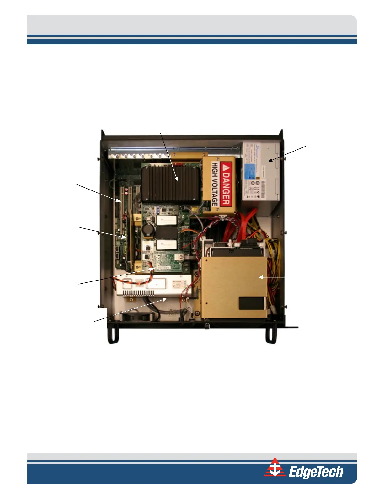
The electronics chassis for the 4200 Rack Mount Topside Processor is depicted in
Figure 1-2. A block electronics diagram for the topside unit is provided in Figure 2-2.
The main hardware elements in the 4200 Rack Mount Topside Processor include the following
components and circuit boards:
Figure 2-1: 4200 Rack Mount Processor Chassis
2.1.1.1 Power
The Powerboard inputs +24 VDC on J1 from the 24 VDC Power Supply and generates the 400 VDC tow
vehicle power. This is the output to the tow vehicle on J13 combined with the frequency shift keyed (FSK)
responder trigger signal input on J10 and the ADSL downlink command and uplink data signals.
The command signals are input, and the data signals are output on J14. The Powerboard also includes +5,
+12 and +15 VDC power supplies, where +12 VDC is output on J4 to the fan and on J6 to the ADSL Modem
board.
supply
Supply