5-11
5.4.3 701-DL Digital Lin
Green POWER indicator on
the topside does not
illuminate when the unit is
turned on.
The POWER switch is not turned
on.
Verify the POWER switch is on.
No AC Power. When using the
AC power connector.
Verify the topside processor is connected
to AC power. Check the AC power source.
Verify that the fuse is good.
5-amp Fuses on the rear panel of
topside ac connection bad.
Check fuses for continuity. Replace if
necessary.
The indicator is not operating.
Open the topside processor and check the
indicator and wiring.
The Green LAN indicator on
the topside does not
illuminate when the unit is
turned on.
There is no connection between
the topside and the computer.
Check LAN connections between topside
and laptop.
The indicator is not operating.
Open the topside processor and check the
indicator and wiring.
Green LINK indicator on the
topside flashes when the
topside is turned on.
After 1-minute flashing
should stop, and the
indicator should remain lit.
Tow cable between topside and
Towfish is disconnected or
Check connections and tow cable.
Modem settings on the topside
are incorrect.
Refer to APPENDIX C for modem settings.
Check topside on different Towfish.
Table 5-3: 701-DL Troubleshooting Guide
5.5 Tow Vehicle Troubleshooting Guide
The 4200 Tow Vehicle is a complex computer-controlled system that requires engineering expertise and
the proper test equipment to service. For any service or troubleshooting, please contact EDGETECH
CUSTOMER SERVICE for updated instructions, drawings, documentation, tools, and guidance. This
ensures success and is necessary to maintain the product’s warranty.
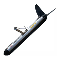
The 4200 Towfish is a software-controlled computer system that includes both digital and analog
connections between components. Many of the digital connections share and are dependent on the same
data and address lines, so the failure of one component may cause others to fail. Therefore, to
successfully troubleshoot an issue, it is best to understand the dataflow and methodically test to isolate
the problem.
An example methodical test procedure is as follows:
1. Ensure that the system is properly installed with all cables connections mated with connectors.
2. Check that fuses have not blown and that the lines connecting them are to the specified electrical
limits. Fuses may fail if a wrong connection has been made during setup. They have also been
known to fail for no apparent reason. Always replace fuses with those of the same value. If a fuse
fails again within a short time, there are more serious problems within the corresponding unit.

 Loading...