49 Installation and Service Guide: Printer Controller EB-34
Replacing Parts
• Reset button: J20, pins 5 (green cable) and 7 (white cable)
Figure 18: Cable connections for power button
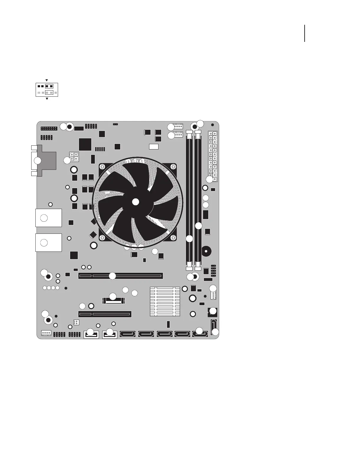
Figure 19: Diagram of the EB-34 motherboard
1 DVD drive connector (SATA0) 8 Scan crossover connector (10/
100BaseT), USB connectors (x2)
13 CPU fan connector (CPUFAN J17)
2 Security chip (J12) 14 Chassis fan connector (SYSFAN J23)
3 Battery (BT1) 9 Network connector (10/100/
1000BaseT), USB connectors (x2)
15 DVI+VGA port
4 Copier interface board (PCIE x16) 16 For front panel USB port (USB A2)
5 Power and reset button pins (J20) 10 CPU and cooling assembly 17 For UIB cable (USB A1)
6 DIMM (DIMM A1) 11 24-pin power connector (ATX24P_1) 18 For hard disk drive data cable (SATA1)
7 DIMM (DIMM A0) 12 4-pin power connector (J24) MS Mounting screws
Note: Any connectors not listed above are not used.
1
2
9
10
Power button
Reset button
1
14
11
15
MS
MS
MS
MS
13
MS
12
3
4
5
6
7
8
9
2
10
18
1716