EasyManuals Logo

EG4 18KPV User Manual

EG4 18KPV
95 pages
To Next Page IconTo Next Page
To Previous Page IconTo Previous Page
Page #23 background imageLoading...
Page #23 background image
22
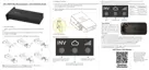
Please refer to the connection dia-
gram to the left for the correct posi-
tion of the CTs. Clamp the 2 CTs onto
the L1 and L2 wires at the service en-
try point in the main service panel.
The arrows on the CTs must point to-
ward the inverter and be placed on the
proper line based on their number. (CT
1 for L1, CT 2 for L2)
Pin 1 2 3 4 5 6 7 8
Pin
Description
1-4
Reserved
5
CT2N
6
CT2P
7
CT1N
8
CT1P
CT Clamp Ratio
The inverter supports three ratios
of CT clamps - 1000:1, 2000:1,
and 3000:1. The CT ratio of the
included CTs is 3000:1.
If you are using a third-party CT,
please ensure that the CT ratio is
one of the supported types. Select
the correct CT ratio setting on the
inverter monitoring page or on
the inverter LCD.
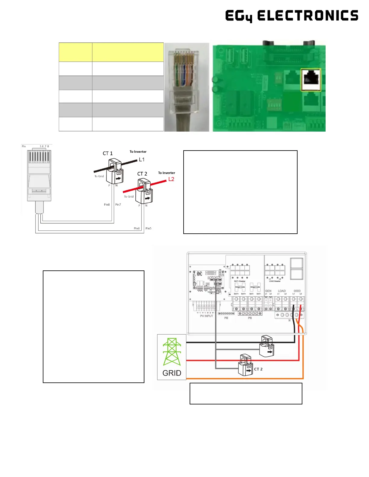
In the above diagram, Black wire is L1,
Red is L2 and Orange is Neutral.
CT 1

Table of Contents

Other manuals for EG4 18KPV

Questions and Answers:

Question and Answer IconNeed help?

Do you have a question about the EG4 18KPV and is the answer not in the manual?

EG4 18KPV Specifications

General IconGeneral
ModelEG4 18KPV
CategoryInverter
Rated Power18 kW
Max. AC Output Current75A
Surge Power36 kW
Number of MPPTs2
Frequency50/60 Hz
Operating Temperature-25°C to 60°C
Warranty5 years
Output Voltage120/240VAC
CommunicationRS485
CoolingFan
Weight77 lbs (35 kg)
Dimensions670 x 530 x 220 mm

Related product manuals