27
4.9
Parallel System Connection
4.9.1 Connections for Parallel System
The hybrid inverter supports parallel connection to expand power and energy capacity to suit different
usage scenarios. Up to 10 units can be paralleled to reach a capacity of 120kW.
The parallel wiring diagrams are as follows. The manual bypass switch connects the loads to LOAD panel
as default. If the inverters fail, users can switch the loads to utility.
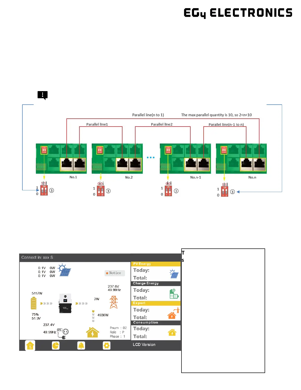
Remember!
Put the CAN communication PIN to ON status for the first and the last inverter and OFF for inverters in between.
Note: Both switches in the “ON” position translates to address 1. Both switches in the “OFF” position
translates to address 0.
Please contact your inverter supplier for more detailed guidance on paralleling a system.
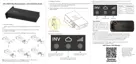
4.9.2 Parallel Information Display
The information in the red box
shows the parallel
information:
• Pnum: 01 – 10
a. Display number of parallel
units
• Role: P or S:
a. P means Master
b. S means Slave
• Phase: 1 – 3:
a. 1: U Phase
b. 2: V Phase
c. 3: W Phase