17
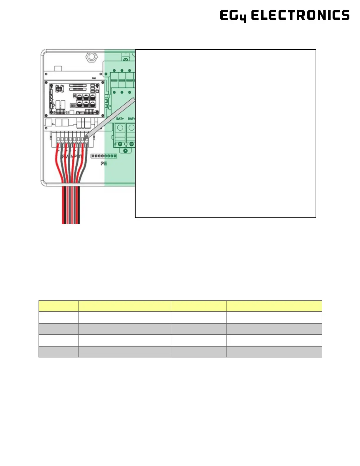
4.4.3 Steps for PV Wiring
Note: According to the NEC (National Electric Code) in the USA all PV Systems above 50V must have one current-carry-
ing conductor connected to the ground/earth. With that, all exposed metal parts of the system must be grounded re-
gardless of voltage. DO NOT GROUND NEGATIVE PV LINE, ONLY SOLAR PANEL FRAMES.
4.5
Battery Connection
4.5.1 Connecting Batteries to the Inverter
Cable Requirements (suggestions based on distance and battery bank quantity):
Torque for cable connection
1/0 AWG (53.5 mm
2
) 10 ft. 165 in. lbs. (16.6 Nm)
2
4/0 AWG (107 mm
2
) 10 ft. Max. 275 in. lbs. (31.1 Nm)
2
Max. 275 in. lbs. (31.1 Nm)
1. Ensure all breakers and disconnect switches are in the OFF
position before connecting or disconnecting wires. Use a
voltmeter to confirm there is no voltage present.
2. Strip off 1/4 – 5/16 in. (6 – 8 mm) insulation on the PV
string’s positive and negative conductors.
3. Use wire ferrules for the PV string conductors if they are
stranded wire.
4. Insert the conduit fitting into the opening for the PV con-
nection and tighten it from the inside using the counter
nut.
5. Route the PV conductors through the conduit fitting and into
the inverter.
6. Secure the PV conductors in place into the inverter inputs.
Verify that they are secured properly by lightly pulling on
them.
7. Ensure the conduit and conduit fittings are fastened reliably
and the cable entry holes are sealed.