88
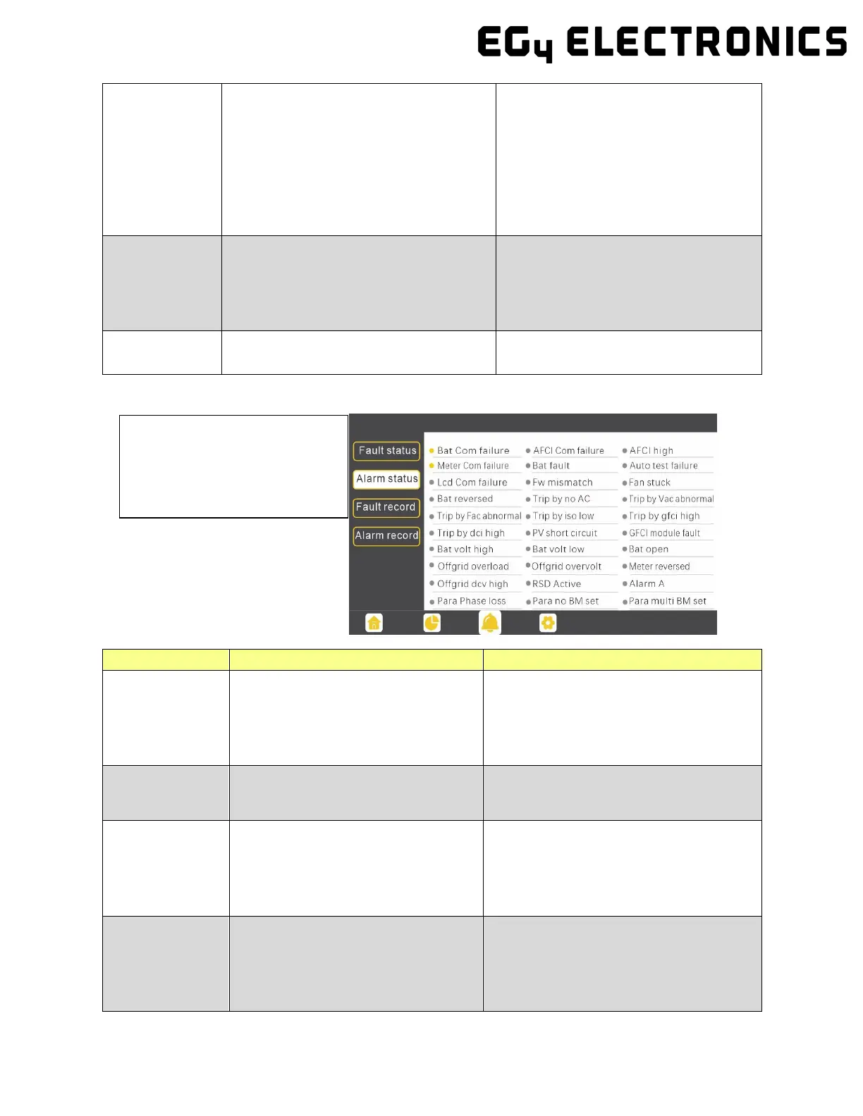
If the dot to the left of the fault
item is yellow, it means the fault
is active. When it is grey, it
means the fault is inactive.
Para Phase set
error
Incorrect setting of phase in parallel
First confirm the wiring for the parallel
system is correct. Once verified, con-
nect each inverter to the grid. The sys-
tem will automatically detect the
phase sequence and the fault auto-
matically resolves after the phase se-
quence is detected. If the fault
persists, contact your supplier.
Para Gen in
cord
Inconsistent generator connection in
parallel
Some inverters are connected to gen-
erators, and some are not. Confirm all
inverters in parallel are connected to
common generator output, or none
are connected to generators.
Para sync loss Parallel inverter fault
Restart the inverter. If the fault per-
sists, contact your supplier.
12.3.2 Alarm on the LCD and Alarm List
Alarm List
Bat com failure
Inverter fails to communicate with
battery
Check if the communication cable pinout
is correct, and if you have chosen the cor-
rect battery brand on the inverter’s LCD.
If all is correct but this alarm
persists, contact your supplier.
AFCI com failure
Inverter fails to communicate with
AFCI module
Restart inverter. If the error continues,
contact your supplier.
AFCI high
PV arc fault is detected
Check each PV string for correct open-
circuit voltage and short-circuit current. If
the PV strings are in good condition,
please clear the alarm on the inverter
Meter com
failure
Inverter fails to communicate with
the meter
1. Check if the communication cable is
connected correctly and in good
working condition.
2. Restart inverter. If the alarm persists,