29
5. Add some small loads to the load output and verify power output.
6. Finish the commissioning.
4.10
Grid, Load, and AC Connection
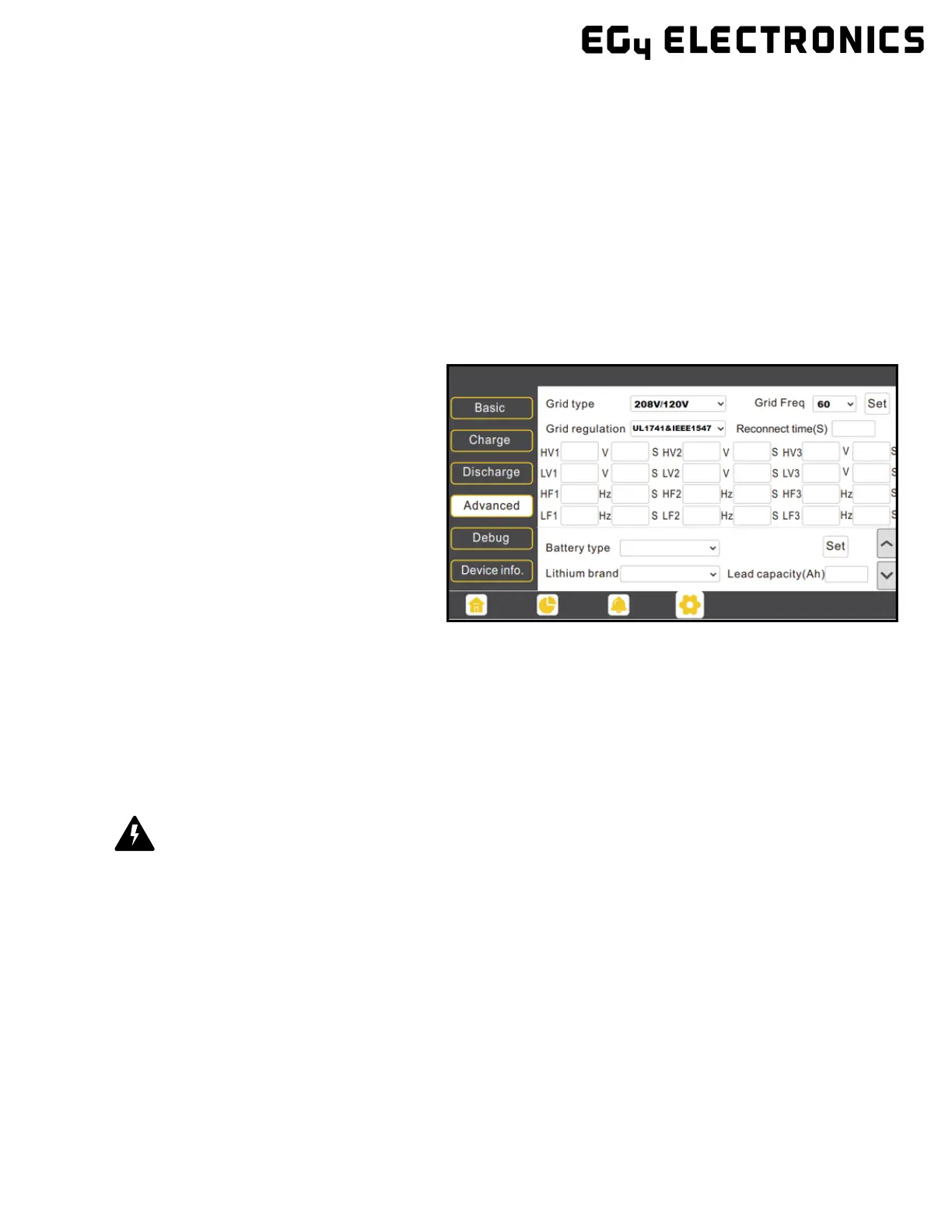
4.10.1 Grid Type and Regulation Connection
This inverter can be used in 120/240V or 120/208V phase systems. This inverter has passed the main
grid connection regulations in the U.S.
Users can choose the different grid type and regulation in the ‘Advanced’ program, as shown in the im-
age below.
5 Grid and Load Con-
nections for Split-
Phase Service
The inverter can withstand up to 8kW of im-
balance between L1 and L2. However, the
loads should be balanced as much as possible
to avoid damaging the load side equipment.
The connection diagrams for 120/240V service
are shown in the following pages. The connec-
tion diagram for 120/208V service is roughly
the same except that the generator input is
not supported.
The inverter can be connected to the load side of the service disconnect. This means if the busbar rating
in the main panel must meet the NEC705.12(B)(3) requirements. Otherwise, a Line side connection can
be made to avoid an expensive main panel upgrade.
5.1
Decision Tree and Wiring Diagrams
Danger
There is a very real danger of overloading the service entrance wires with supply side taps. (Refer to
NEC 220.) Users could essentially be adding loads to a possibly already fully loaded service entrance.
DO THIS ONLY UNDER ADVISEMENT OF YOUR ELECTRICIAN AND/OR INSPECTOR.