49
AC Couple
The inverter supports AC coupling connection with the existing grid-interactive solar system. The ex-
isting solar system is connected to the inverter's GEN terminal. Please see section 4.8.1 for further
information.
• AC Couple Start Volt(V)/SOC(%): AC Coupling will start at this set V/SOC.
• AC Couple End Volt(V)/SOC(%): AC Coupling will stop at this set V/SOC.
7 Installer Settings
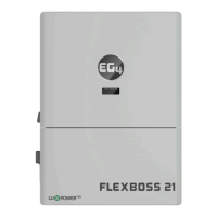
7.1
Common Settings
• Time: Set the time/date of the inverter. The input format is 2019-02-14 14:44:00. Format
YYYY-MM-DD HH:MM:SS
• MODBUS Addr: Configure COM address in the RS-485 communication system. If you install
more than one inverter in the field and use an RS-485 bus to communicate, you need to set
the inverters to different address. Addresses range from 0-150.
• PV Input Mode: The connection type of solar modules.
• Neutral Detect Enable/Disable: Detects if the customer has connected the Neutral line to
the AC Input terminal.
Model
• Measurement: Choose the correct measurement, Meter Type or CT Sample Ratio according
to the external measuring device you installed. The default measurement is CT with sample
ratio: 1000/1, and you can adjust the measurement if you have installed a meter to the in-
verter.
• Battery Type: Choose the battery type and then select Lithium Brand (for closed-loop com-
munications), or battery capacity for lead-acid/lithium batteries with no communications.
Please note after setting the battery type, all other settings will reset to default.
Note: When you need to change the “Model” settings, you need to set inverter to “Standby”
first, and then press “Set Battery” to change the model.
•
Lead-acid Capacity: Set your total capacity when using Lead-Acid batteries.