21
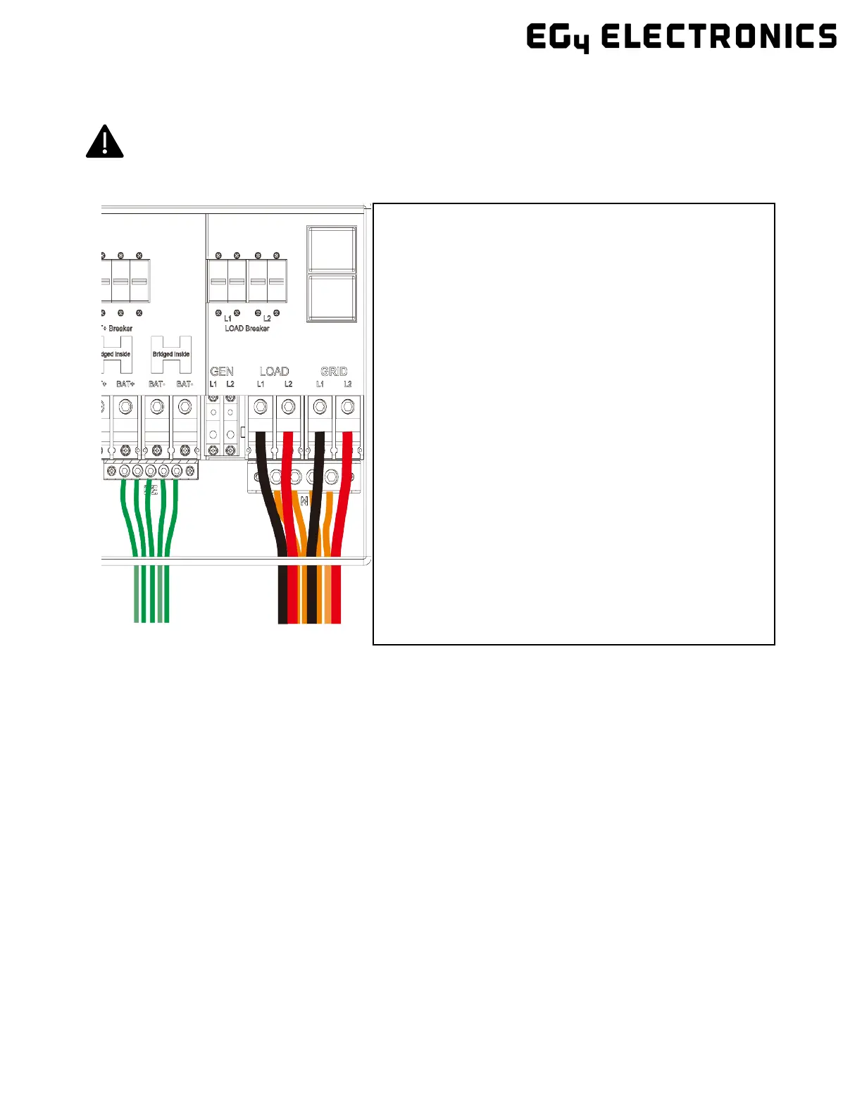
4.5.5 Steps for AC Connection
Reminder
After connecting all AC wiring, put the built-in LOAD breaker back to the ON position before providing
power to the load.
4.5.6 CT/Meter Connection
To measure the power imported from and exported to the grid, a pair of CTs or one, three-phase meter
must be installed at the service entry point in or near the main service panel. Two CTs are provided with
each inverter.
CT Port Pin Definition
The CT interface for the two (2) CT connections is an RJ45 port. The two (2) CTs come with premade
plugs, so they can be connected directly to the port.
1 Before connecting or disconnecting AC wires, ensure
all breakers are in the OFF position. Check that there is
no voltage present with a voltmeter.
2 Strip off 5/16–3/8 in. (8–10 mm) insulation from the AC
cables.
3 Use wire ferrules if the cables are made of fine stranded
wires.
4 Secure the conduit fitting to the enclosure using the
counter nut of the fitting.
5 Fasten the GRID and LOAD cables to the terminal block
in accordance with the terminal labels using an M8 hex
wrench. (For ground terminal, use an M5 hex wrench.)
See section 4.5.4 for torque information
6 Secure conduit to the conduit fitting.
7 Check that the cables are connected properly. Take
appropriate measures to ensure that the conduit and
conduit fitting are properly secured and seal the cable
entry holes.