EMC VPLEX with GeoSynchrony 4.1 Installation and Setup Guide
16
Introduction
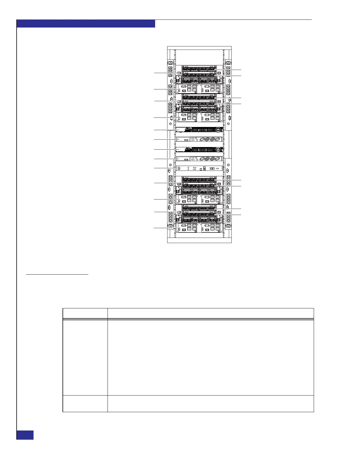
Figure 3 VPLEX hardware example: Quad-engine configuration
Major components
Table 1 describes the major hardware components in a VPLEX cluster.
ON
I
OFF
O
ON
I
OFF
O
ON
I
OFF
O
ON
I
OFF
O
ON
I
OFF
O
ON
I
OFF
O
ON
I
OFF
O
ON
I
OFF
O
ON
I
OFF
O
ON
I
OFF
O
ON
I
OFF
O
ON
I
OFF
O
SPS 1
Engine 1
UPS A
Fibre Channel switch A
Fibre Channel switch B
Management server
Director 1A
Director 1B
SPS 2
Engine 2
SPS 3
Engine 3
SPS 4
Engine 4
Director 2A
Director 2B
Director 3A
Director 3B
Director 4A
Director 4B
UPS B
Zep-06
Table 1 Major VPLEX hardware components
Component Description
Engine (shown in
Figure 4 on page 17)
Contains the following:
• Two directors, each running VPLEX GeoSynchrony™ software and containing four Fibre Channel I/O
modules. Two I/O modules are dedicated to front-end host connections, and two are dedicated to
back-end storage connections. Each I/O module contains four 8 Gb/s Fibre Channel ports.
• I/O module carrier, containing two Fibre Channel I/O modules (one for each director) for intersite and
intrasite communication. Each I/O module provides four Fibre Channel ports.
• CPU module.
• Two 30 GB solid state drives (SSDs), one for each director.
• Two management modules
• Two redundant power supplies
• Four fans
Standby power
supply (SPS)
Provides backup power (through a pair or redundant modules) that allows an engine to ride through transient
(30 seconds or less) power loss.