EMC VPLEX with GeoSynchrony 4.1 Installation and Setup Guide
28
Installing the Hardware
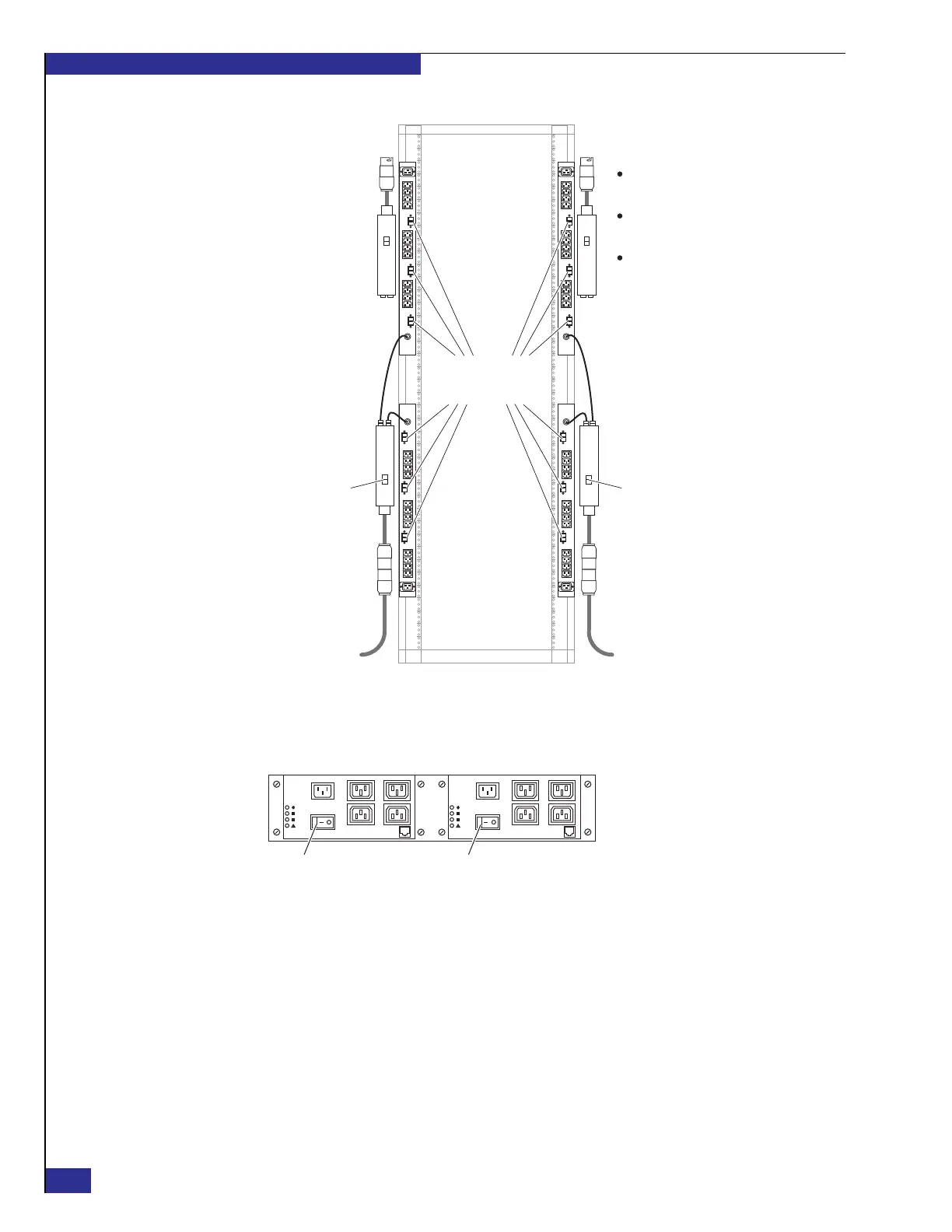
Figure 13 Cabinet power switches and circuit breakers
4. Switch all SPS power switches (shown in Figure 14)ON.
Figure 14 SPS power switches
5. Switch both lower PDPs ON.
6. Switch ON each PDU circuit breaker that has components plugged into its power
strip. (Figure 64 on page 91 identifies the circuit breaker associated with each
power strip.)
7. Verify that the LED status on each SPS and director is as shown in Figure 15 on
page 29.
Generally, the SPS On-Battery LED stays on while the SPS units fully charge
(which could be a few minutes or a few hours, depending on the state of the
battery). If any amber LED not related to the SPS recharge remains on for
more than 10 minutes, verify that the components are cabled correctly.
Zep-013
The upper PDUs are installed
upside-down from the lower PDUs.
The upper PDPs are installed,
but are not used.
The upper PDUs are not used in a
single-engine configuration.
PDU circuit
breakers
ON
I
OFF
O
ON
I
OFF
O
ON
I
OFF
O
ON
I
OFF
O
ON
I
OFF
O
ON
I
OFF
O
ON
I
OFF
O
ON
I
OFF
O
ON
I
OFF
O
ON
I
OFF
O
ON
I
OFF
O
ON
I
OFF
O
PDP power
switch
PDP power
switch
Notes:
To 30 A, 220 VAC
power source 1
To 30 A, 220 VAC
power source 2
CL4171-zep
ON ON