EMC VPLEX with GeoSynchrony 4.1 Installation and Setup Guide
24
Installing the Hardware
Task 4: Connect the
front-end and
back-end cables
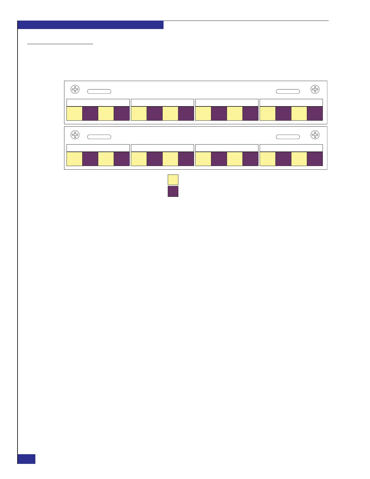
Connect customer-supplied Fibre Channel cables from the front-end and back-end
SANs to the appropriate VPLEX I/O ports (identified in Figure 8).
Figure 8 VPLEX I/O ports
Route the cables horizontally to the sides of the cabinet as shown in Figure 9 on
page 25, to prevent blocking other components in the cabinet. Route the cables up or
down (depending on whether cable entry is though the top or bottom of the cabinet)
the sides of the cabinet through the plastic cable holders, and secure the cables with
the Velcro straps that are attached to the cabinet frame. Maintain a minimum radius
of two inches for any bend in a Fibre Channel cable.
Zep-004e
= Fabric A
= Fabric B
FC01
FE
FC02
FE
FC03
FE
FC00
FE
IOM B0
FC01
FE
FC02
FE
FC03
FE
FC00
FE
IOM B1
FC01
BE
FC02
BE
FC03
BE
FC00
BE
IOM B2
FC01
BE
FC02
BE
FC03
BE
FC00
BE
IOM B3
FC01
FE
FC02
FE
FC03
FE
FC00
FE
IOM A0
FC01
FE
FC02
FE
FC03
FE
FC00
FE
IOM A1
FC01
BE
FC02
BE
FC03
BE
FC00
BE
IOM A2
FC01
BE
FC02
BE
FC03
BE
FC00
BE
IOM A3
Director A
Director B
IOM = I/O module
FE = Front-end SAN port
BE = Back-end SAN port