VPLEX overview
17
Introduction
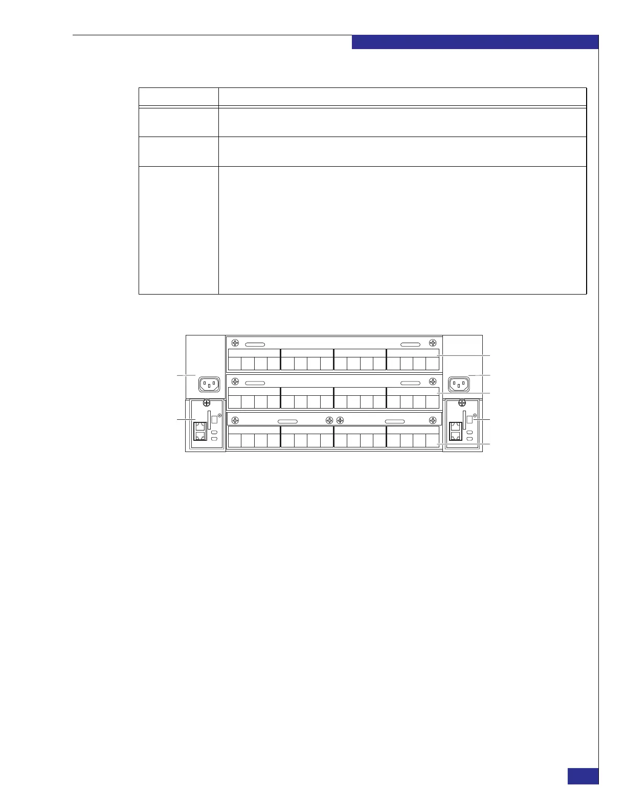
Figure 4 Engine components
Fibre Channel COM
switches
Provide highly available connectivity among the directors in a dual-engine or quad-engine cluster.
Uninterrupted power
supplies (UPS)
Provide backup power to the COM switches and management server in a dual-engine or quad-engine
cluster, allowing the connected components to continue operating through a power loss of up to 30 seconds.
Management server Provides management to the other components in the cluster, and provides an interface for access from a
remote management station.
Management server functions include:
• Hosting VPLEX software.
• Providing an interface between the customer and the VPLEX cluster.
• Generating Call Home events.
• Enabling secure management between clusters in a Metro-Plex.
• Protecting the internal management network from the customer LAN.
• Providing access to VPLEX components for field-replaceable unit (FRU) replacement procedures.
• Facilitating nondisruptive upgrades (NDU)
Table 1 Major VPLEX hardware components
Component Description
Zep-004a
0
F
1
F
3
F
2
F
IOM B0
0
F
1
F
3
F
2
F
IOM B1
0
B
1
B
3
B
2
B
IOM B2
0
B
1
B
3
B
2
B
IOM B3
0
F
1
F
3
F
2
F
IOM A0
0
F
1
F
3
F
2
F
IOM A1
0
B
1
B
3
B
2
B
IOM A2
0
B
1
B
3
B
2
B
IOM A3
0
L
1
L
3
W
2
W
IOM B4
0
n
1
n
3
n
2
n
IOM B5
0
L
1
L
3
W
2
W
IOM A4
0
n
1
n
3
n
2
n
IOM A5
IOM = I/O module
F = Front-end SAN port
B = Back-end SAN port
L = Local COM port
W = WAN COM port (for multi-cluster plex)
n = not currently used
Director A
Director B
I/O module carrier
Side A mgmt. module
Side B
mgmt. module
Power supply B Power supply A