Installing a cluster
29
Installing the Hardware
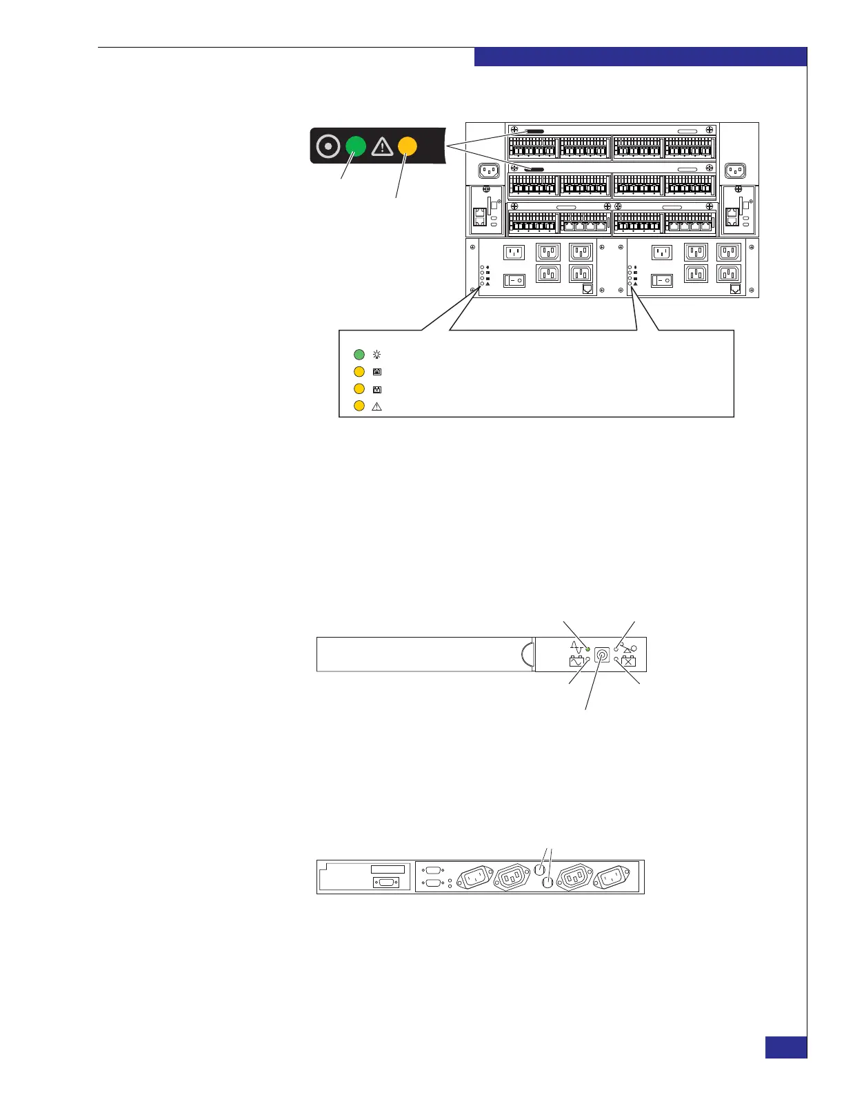
Figure 15 SPS and director LEDs
8. If the cluster is dual-engine or quad-engine:
a. Verify that the Online LED on each UPS (shown in Figure 16) is illuminated
(green), and that none of the other three LEDs shown in Figure 16 is
illuminated.
If the Online LED on either UPS is not illuminated, push the power button,
and verify that the LED is illuminated before proceeding.
Figure 16 UPS, front view
b. Verify that neither circuit breaker (shown in Figure 17) on either UPS has
triggered. If a circuit breaker has triggered, press it to reseat it.
Figure 17 UPS, rear view
Zep-011a
Steady green
Amber during POST, off
during normal operation
Director LEDs
On-line Enabled (LED on) or On-line Charging (LED flashing)
On-Battery
Replace Battery
Internal Check
SPS LEDs:
sym-001521z
Online LED
Overload LED
On battery LED Replace battery LED
Power button
Zep-036a
Circuit breakers