Installing a cluster
27
Installing the Hardware
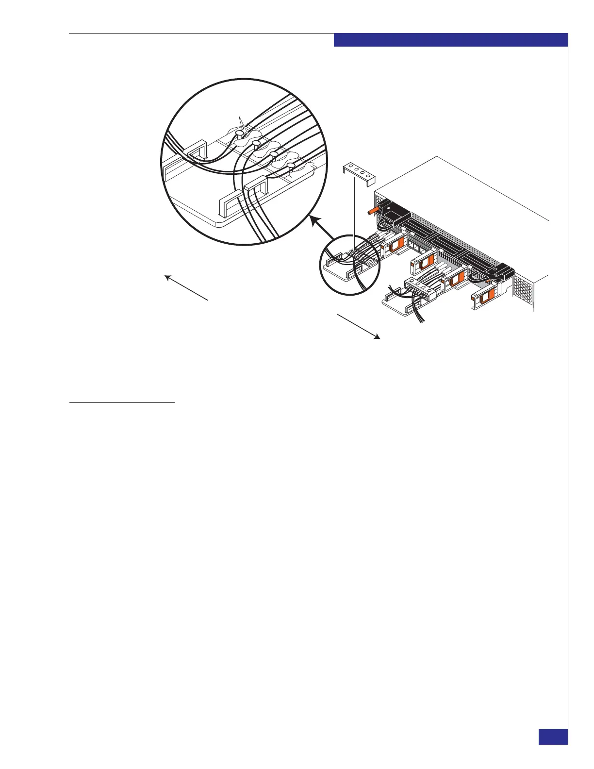
Figure 12 WAN cable routing on cable holders
Task 7: Power the
components ON
1. Verify that all PDP switches and PDU circuit breakers (shown in Figure 13 on
page 28) are in the OFF position. As the figure notes, the upper pair of PDUs are
installed upside-down from the lower pair, and the upper PDPs are not used.
2. Complete the EMC AC Power Configuration Worksheet and place it in a convenient
location, for use in verifying the data center power schemes.
3. Connect the main AC power cables from the lower PDPs into the site’s power
sources. To ensure high availability, each cable must connect to a different power
source, as described in the EMC Best Practices Guide for AC Power Connections in
Two-PDP Bays.
zep-070a
0
1
2
3
0
1
2
3
0
1
2
3
0
1
2
3
0
1
2
3
0
1
2
3
I/O Module A4
0
1
2
3
0
1
2
3
1
2
0
Detail
Separate wires
around posts
Remove cap to route
cables, and then
replace cap
3
Route cables from ports A4-FC02
and B4-FC02 to B side
Route cables from ports
A4-FC03 and B4-FC03 to A side