Product Introduction
Liebert
®
SRC
™
User Manual 12
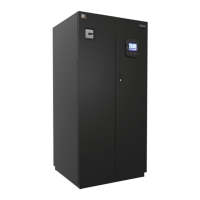
Figure 2-3 Thermostat parts and functions
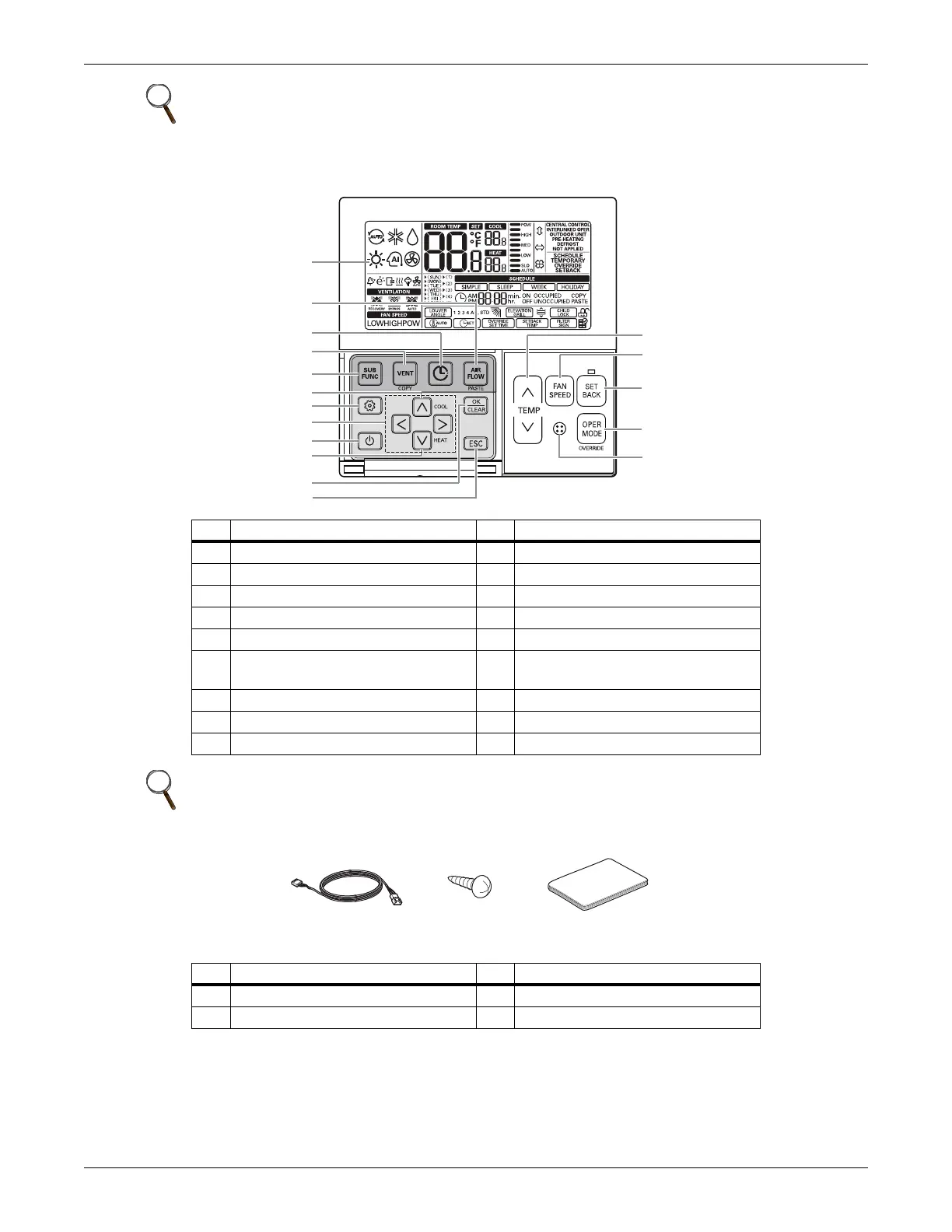
Figure 2-4 Accessories
NOTE
The number and location of operation lamps may vary by unit model.
The features may vary by model.
No. Description No. Description
1 Operation indication 10 Air-flow button
2 Set temperature button 11 Cooling temperature setpoint
3 Fan speed button 12 Function setting button
4 Set back button 13 Up, down, left and right buttons
5 Operation-mode select button 14 On/Off button
6
Wireless thermostat receiver
(not included on some models)
15 Heating temperature setpoint
7 Sub function button 16 Set/Cancel button
8 Ventilation button 17 Exit button
9 Reservation button
NOTE
Some functions may not be available or displayed depending on unit type.
No. Description No. Description
1 Connection cable, 1 each, 32 ft (10 m) 3 User Manual
2 Screw, 4 each
1
7
8
9
10
11
13
12
14
15
16
17
2
3
4
5
6
Connection Cable
(1EA, 32ft (10m))
Screw
(4 EA)
Installation & Operation
Manual