Installation
27 Liebert
®
SRC™ User Manual
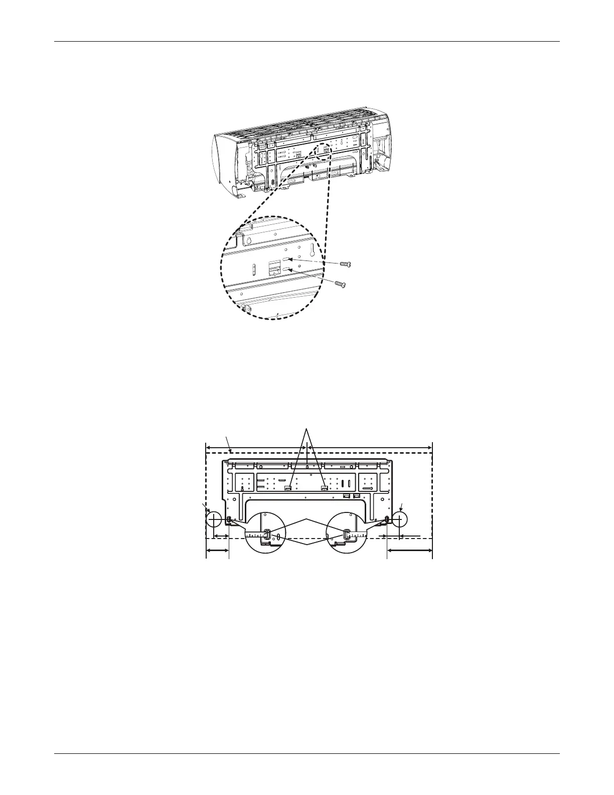
1. Before installation of the plate, confirm the position of the screw types (A or B) between the chassis
and the installation plate, Figure 3-9.
Figure 3-9 Installation-plate screws for SRC18
2. Depending on indoor-unit model refer to Figure 3-10 and mount the plate as follows:
• Use the provided screws and mount the installation plate horizontally by aligning the centerline
using a leveling tool.
• Observe the left and right rear piping clearance when drilling into the wall.
Figure 3-10 Piping clearance for SRC18 plate
Unit: Inch
Ø2-19/32
Ø2-19/32
2 -11/16
2-3/16
Right rear
piping
Left rear
piping
Installation Plate
Measuring Tape
Measuring Tape
Hanger
Place a level on raised tab
Unit Outline
8-3/32
4-3/32
18-3/32 22-13/32