Emerson Process Management GmbH & Co. OHG1-12
X-STREAM X2FD
Instruction Manual
HASXMDE-IM-EX
01/2015
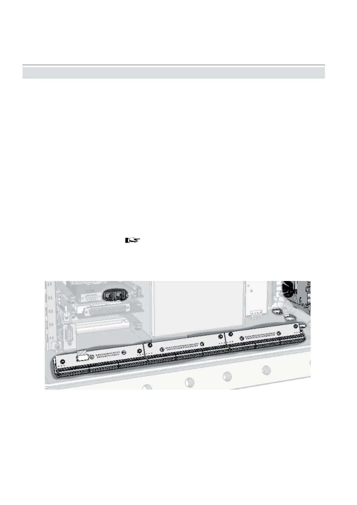
Fig. 1-5: Signals terminals
1.7 Technical Data
Signal inputs and outputs
All signal cables are connected to internal
screw-type terminals (fi g. 1-5),
except the optional RJ45 ethernet connector.
Cable cross-section: max. 1.5 mm
2
(14 AWG),
end sleeves not required.
Cable entry via three IP 68 cable glands or conduits
Permissible cable outer diameter:
see cable gland / conduit specifi cation
Available signals: standard: Analog signal outputs
Relay status signals
Modbus interface (RS232; RS 485)
optional: Digital inputs/outputs
Modbus RJ45 ethernet connector
Detailed terminals confi guration
„Chapter 2
Installation“
Note!
Depending on the actual analyzer confi guration
not all shown terminals may be provided!
 Loading...


