Emerson Process Management GmbH & Co. OHG 2-21
2
Installation
X-STREAM X2FD
Instruction Manual
HASXMDE-IM-EX
01/2015
Pin Signal
P3.1 Input 1
P3.2 Input 2
P3.3 Input 3
P3.4 Input 4
P3.5 Input 5
P3.6 Input 6
P3.7 Input 7
P3.8 GND for Inputs 1-7
P3.9 not used
P3.10 Output 5, NC
P3.11 Output 5, NO
P3.12 Output 5, COM
P4.1 Output 6, NC
P4.2 Output 6, NO
P4.3 Output 6, COM
P4.4 Output 7, NC
P4.5 Output 7, NO
P4.6 Output 7, COM
P4.7 Output 8, NC
P4.8 Output 8, NO
P4.9 Output 8, COM
P4.10 Output 9, NC
P4.11 Output 9, NO
P4.12 Output 9, COM
P2.1 Output 10, NC
P2.2 Output 10, NO
P2.3 Output 10, COM
P2.4 Output 11, NC
P2.5 Output 11, NO
P2.6 Output 11, COM
P2.6 Output 12, NC
P2.8 Output 12, NO
P2.9 Output 12, COM
P2.10 Output 13, NC
P2.11 Output 13, NO
P2.12 Output 13, COM
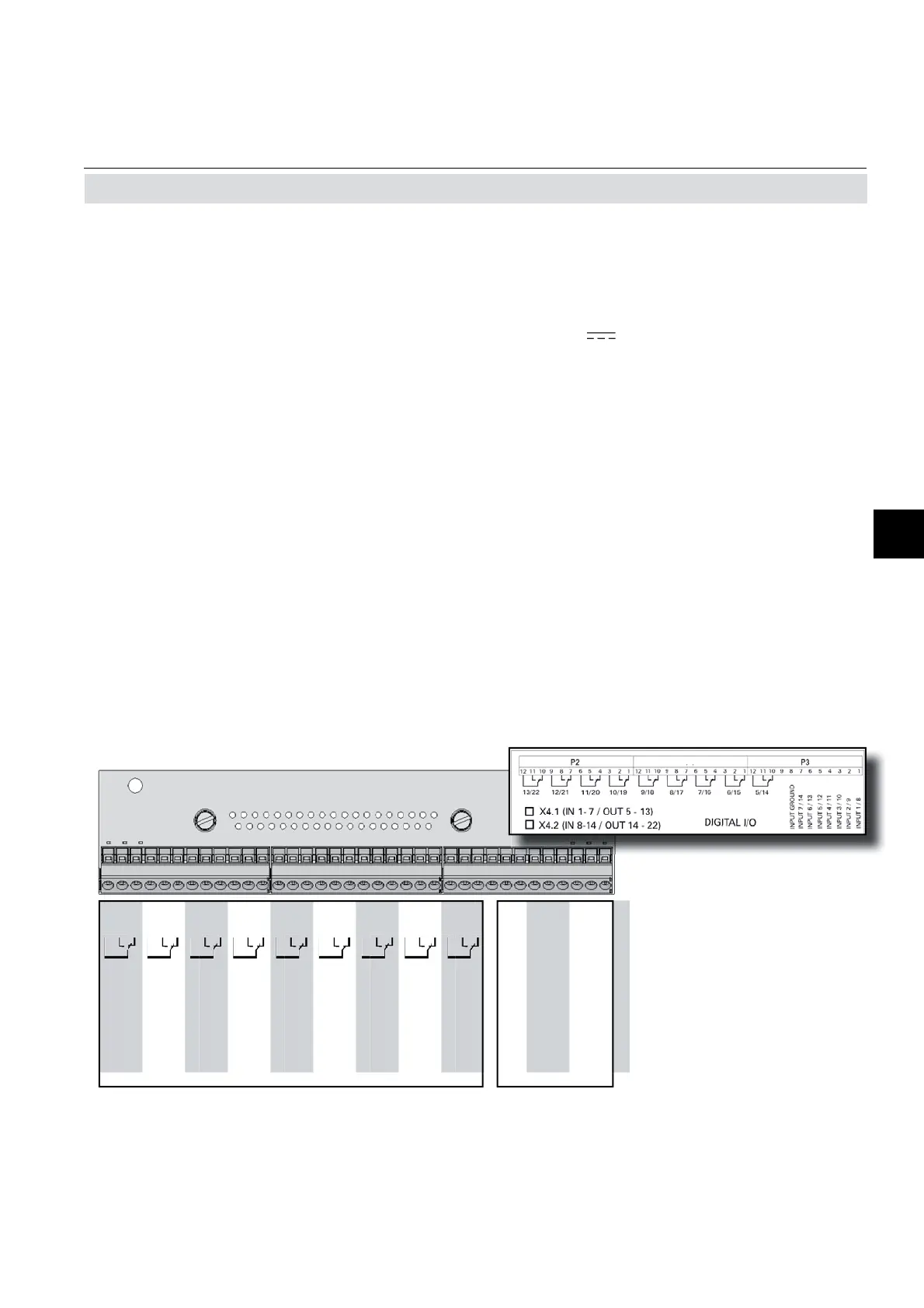
Digital Inputs Digital Outputs
Fig. 2-14: Terminal blocks X4.1 and X4.2 - Digital inputs and outputs
2.5 Installation - Electrical
Note!
Take care of the special installation instruc-
tions in section 4.5 of the X-STREAM gas
analyzer series manual!
Digital inputs
Quantity: 9 (1 terminal block) or
18 (2 terminal blocks), dry change-over
relay contacts, can be used as NO or NC
Electrical specifi cation: max. 30 VDC, 1 A, 30 W
Quantity: 7 (1 terminal block) or
14 (2 terminal blocks)
Electrical specifi cation: max. 30 V
, internally limited to 2.3 mA
H Signal: min. 4 V;
L Signal: max. 3 V
common ground (GND), electrically
isolated from chassis earth
Digital outputs
Notes!
Depending on confi guration, an analyzer can
be fi tted with up to two of these terminal blocks
(the unit will then feature 14 digital inputs and
18 digital outputs). To aid identifi cation, the
sockets are labelled X4.1 and X4.2.
Note!
The confi guration illustra-
ted here is that of the fi rst
adapter, labelled X4.1.
Inputs 8-14 and outputs
14-22, if available, are on
the second adapter X4.2,
see label above).
P4
 Loading...


