Safety
Information
Introduction
Product
Information
System
configuration
Mechanical
Installation
Electrical
Installation
Getting
Started
Basic
parameters
Running
the motor
Optimization
SMARTCARD
operation
Onboard
PLC
Advanced
parameters
Technical
Data
Diagnostics
UL Listing
Information
100 Unidrive SPM User Guide
www.controltechniques.com Issue Number: 3
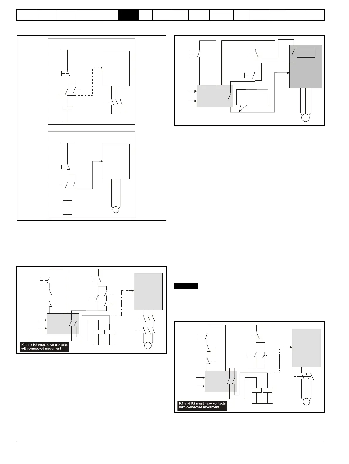
Figure 6-45 Start / stop control EN954-1 category B - replacement
of contactor
In the second example, illustrated in Figure 6-46 and Figure 6-47, a
conventional high-integrity system which uses two safety contactors with
auxiliary contacts with connected movement is replaced by a single
SAFE TORQUE OFF (SECURE DISABLE) system. This arrangement
meets EN954-1 category 3.
Figure 6-46 Category 3 interlock using electromechanical safety
contactors
The safety function of the example circuit is to ensure that the motor
does not operate when the interlocks are not signalling a safe state. The
safety relay is used to check the two interlock channels and detect faults
in those channels. The stop/start buttons are shown for completeness as
part of a typical arrangement, they do not carry out a safety function and
are not necessary for the safe operation of the circuit
Figure 6-47 Category 3 interlock using SAFE TORQUE OFF
(SECURE DISABLE) with protected wiring
In the conventional system, a contactor failure in the unsafe direction is
detected the next time the safety relay is reset. Since the drive is not part
of the safety system it has to be assumed that AC power is always
available to drive the motor, so two contactors in series are required in
order to prevent the first failure from causing an unsafe event (i.e. the
motor driven).
With SAFE TORQUE OFF (SECURE DISABLE) there are no single
faults in the drive which can permit the motor to be driven. Therefore it is
not necessary to have a second channel to interrupt the power
connection, nor a fault detection circuit.
It is important to note that a single short-circuit from the Enable input
(STO) to a DC supply of approximately +24V would cause the drive to be
enabled. For this reason, Figure 6-47 shows the wire from the Enable
input to the safety relay as "protected wiring" so that the possibility of a
short circuit from this wire to the DC supply can be excluded, as
specified in ISO 13849-2. The wiring can be protected by placing it in a
segregated cable duct or other enclosure, or by providing it with a
grounded shield. The shield is provided to avoid a hazard from an
electrical fault. It may be grounded by any convenient method, no
special EMC precautions are required.
If the use of protected wiring is not acceptable, so that the possibility of
this short circuit must be allowed for, then a relay must be used to
monitor the state of the Enable input, together with a single safety
contactor to prevent operation of the motor after a fault. This is illustrated
in Figure 6-48.
N
The auxiliary relay K2 must be located in the same enclosure and close
to the drive, with its coil connected as closely as possible to the drive
enable (STO) input.
Figure 6-48 Use of contactor and relay to avoid the need for
protected wiring
For further applications guidance, refer to the Unidrive SP Advanced
User Guide.
Stop
Start
Drive
Enable
K1
(or at
drive
output)
K1
+24V
~
K1
Drive
STO
M
Using contactor
Using SAFE TORQUE OFF
(SECURE DISABLE)
T31
T31
3 ~
Stop
Start
K1
+24V
K1
Stop
Start
Drive
Enable
K1
K2
+24V
Safety
relay
Two-channel
interlocks
Reset
K1
K2
K1
K2
K1 K2
M
3 ~
STO
+24V
Safety
relay
Interlocks
Reset
(Pr )
10.02
Protected wiring
(screened or
segregated)
SD
K1
K2
+24V
Safety
relay
Two-channel
interlocks
Reset
K1
K2
K1 K2

 Loading...


