Safety
Information
Introduction
Product
Information
System
configuration
Mechanical
Installation
Electrical
Installation
Getting
Started
Basic
parameters
Running
the motor
Optimization
SMARTCARD
operation
Onboard
PLC
Advanced
parameters
Technical
Data
Diagnostics
UL Listing
Information
Unidrive SPM User Guide 35
Issue Number: 3 www.controltechniques.com
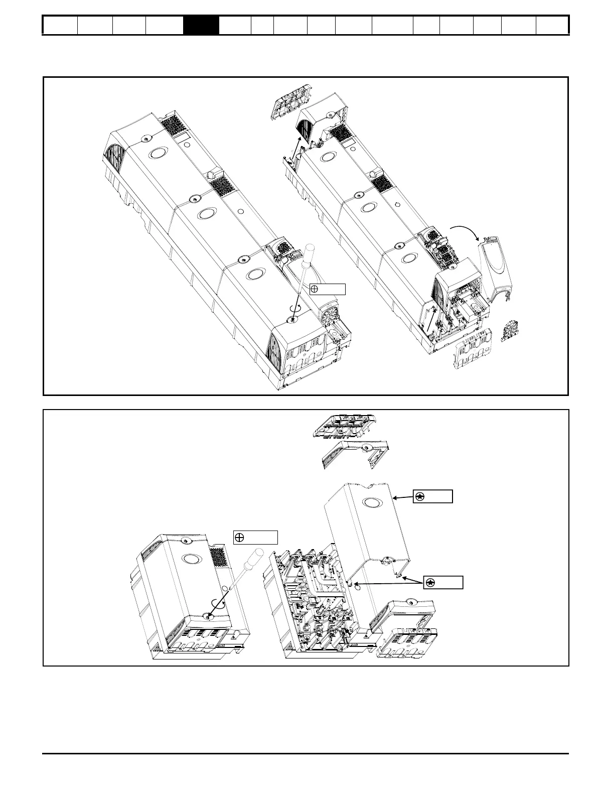
To remove a terminal cover, undo the screw and lift the terminal cover off as shown.
When replacing the terminal covers the screws should be tightened with a maximum torque of 1 N m (0.7 lb ft).
Figure 5-2 Removing the terminal covers (Uni SPMA illustrated)
Figure 5-3 Removing the Unidrive SPMC/U dual rectifier terminal covers and housing
When removing the Unidrive SPMC/U dual rectifier centre housing, undo the 3 x T25 torx head screws as shown in Figure 5-3. When the housing is
replaced, the screws should be tightened with a maximum torque of 2.5 N m (1.8 lb ft).

 Loading...


