Safety
Information
Introduction
Product
Information
System
configuration
Mechanical
Installation
Electrical
Installation
Getting
Started
Basic
parameters
Running
the motor
Optimization
SMARTCARD
operation
Onboard
PLC
Advanced
parameters
Technical
Data
Diagnostics
UL Listing
Information
78 Unidrive SPM User Guide
www.controltechniques.com Issue Number: 3
Minimum resistances and power ratings
Table 6-22 Minimum resistance values and peak power rating for
the braking resistor at 40°C (104°F)
* Resistor tolerance: ±10%
** Continuous rating if drive is part of a common DC bus system. In
parallel systems without the DC bus connected, the resistors must be
matched to within ±5%.
For high-inertia loads or under continuous braking, the continuous power
dissipated in the braking resistor may be as high as the power rating of
the drive. The total energy dissipated in the braking resistor is dependent
on the amount of energy to be extracted from the load.
The instantaneous power rating refers to the short-term maximum power
dissipated during the on intervals of the pulse width modulated braking
control cycle. The braking resistor must be able to withstand this
dissipation for short intervals (milliseconds). Higher resistance values
require proportionately lower instantaneous power ratings.
In most applications, braking occurs only occasionally. This allows the
continuous power rating of the braking resistor to be much lower than
the power rating of the drive. It is essential, though, that the
instantaneous power rating and energy rating of the braking resistor are
sufficient for the most extreme braking duty that is likely to be
encountered.
Optimization of the braking resistor requires a careful consideration of
the braking duty.
Select a value of resistance for the braking resistor that is not less than
the specified minimum resistance. Larger resistance values may give a
cost saving, as well as a safety benefit in the event of a fault in the
braking system. Braking capability will then be reduced, which could
cause the drive to trip during braking if the value chosen is too large.
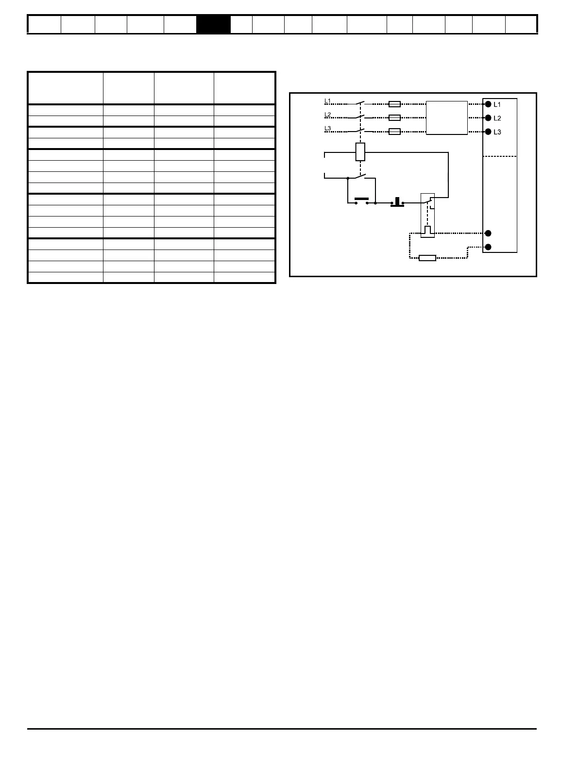
Thermal protection circuit for the braking resistor
The thermal protection circuit must disconnect the AC supply from the
drive if the resistor becomes overloaded due to a fault. Figure 6-17
shows a typical circuit arrangement.
Figure 6-17 Typical protection circuit for a braking resistor
See Figure 6-1 and Figure 6-2 on page 65 for the location of the +DC
and braking resistor connections.
6.11.2 Braking resistor software overload protection
The Unidrive SPM software contains an overload protection function for
a braking resistor. In order to enable and set-up this function, it is
necessary to enter two values into the drive:
• Resistor short-time overload time (Pr 10.30)
• Resistor minimum time between repeated short-time overloads
(Pr 10.31)
This data should be obtained from the manufacturer of the braking
resistors.
Pr 10.39 gives an indication of braking resistor temperature based on a
simple thermal model. Zero indicates the resistor is close to ambient and
100% is the maximum temperature the resistor can withstand. An OVLd
alarm is given if this parameter is above 75% and the braking IGBT is
active. An It.br trip will occur if Pr 10.39 reaches 100%, when Pr 10.37 is
set to 0 (default value) or 1.
If Pr 10.37 is equal to 2 or 3 an It.br trip will not occur when Pr 10.39
reaches 100%, but instead the braking IGBT will be disabled until
Pr 10.39 falls below 95%. This option is intended for applications with
parallel connected DC buses where there are several braking resistors,
each of which cannot withstand full DC bus voltage continuously. With
this type of application it is unlikely the braking energy will be shared
equally between the resistors because of voltage measurement
tolerances within the individual drives. Therefore with Pr 10.37 set to 2 or
3, then as soon as a resistor has reached its maximum temperature the
drive will disable the braking IGBT, and another resistor on another drive
will take up the braking energy. Once Pr 10.39 has fallen below 95% the
drive will allow the braking IGBT to operate again.
See the Unidrive SP Advanced User Guide for more information on
Pr 10.30, Pr 10.31, Pr 10.37 and Pr 10.39.
This software overload protection should be used in addition to an
external overload protection device.
Braking Resistor Connections
This section details the rules that govern the connection of braking
resistors to a parallel application. The braking resistor should be
connected across the brake and +DC terminals.
1. The brake terminals must not be connected together. Each module
must have its own resistor if required.
2. The resistor connected to each module must not have a value less
than the recommended minimum value for that module size.
Model
Minimum
resistance*
Ω
Instantaneous
power rating**
kW
Average power
for 60s
kW
SPMA1401 5 122 122
SPMA1402 5 122 122
SPMA1601 10 125 113
SPMA1602 10 125 125
SPMD1201 2.5 61 61
SPMD1202 2.5 61 61
SPMD1203 1.9 80 80
SPMD1204 1.9 80 80
SPMD1401 5 122 122
SPMD1402 5 122 122
SPMD1403 3.8 160 160
SPMD1404 3.8 160 160
SPMD1601 10 125 113
SPMD1602 10 125 125
SPMD1603 6.2 202 165
SPMD1604 6.2 202 198
Optional
RFI filter
Stop
Start /
Reset
Thermal
protection
device
Braking resistor
Drive
Main contactor
power supply
+DC
BR

 Loading...


