Safety
Information
Introduction
Product
Information
System
configuration
Mechanical
Installation
Electrical
Installation
Getting
Started
Basic
parameters
Running
the motor
Optimization
SMARTCARD
operation
Onboard
PLC
Advanced
parameters
Technical
Data
Diagnostics
UL Listing
Information
Unidrive SPM User Guide 133
Issue Number: 3 www.controltechniques.com
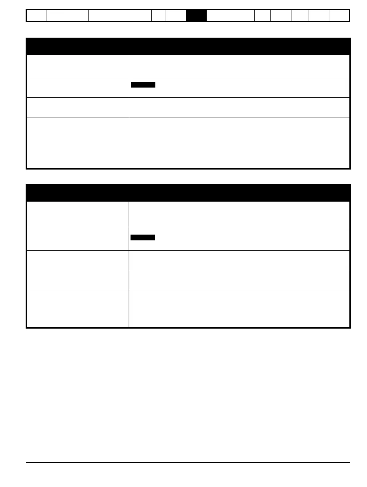
9.6.2 Detailed feedback device commissioning/start-up information
Standard quadrature encoder with or without commutation signals (A, B, Z or A, B, Z, U, V, W), or
Sincos encoder without serial communications
Encoder type Pr 3.38
Ab (0) for a quadrature encoder without commutation signals *
Ab.SErVO (3) for a quadrature encoder with commutation signals
SC (6) for a Sincos encoder without serial communications *
Encoder power supply voltage Pr 3.36
5V (0), 8V (1) or 15V (2)
If output voltage from the encoder is >5V, then the termination resistors must be disabled Pr
3.39
to 0
Encoder number of lines per
revolution
Pr 3.34
Set to the number of lines or sine waves per revolution of the encoder.
See section 9.6.3 Restriction of encoder number of lines per revolution on page 135 for restrictions
on this parameter.
Encoder termination selection
(Ab or Ab.SErVO only)
Pr 3.39
0 = A, B, Z termination resistors disabled
1 = A, B termination resistors enabled and Z termination resistors disabled
2 = A, B, Z termination resistors enabled
Encoder error detection level Pr 3.40
0 = Error detection disable
1 = Wire break detection on A, B and Z inputs enabled
2 = Phase error detection (Ab.SErVO only)
3 = Wire break detection on A, B and Z inputs and phase error detection (Ab.SErVO only)
Termination resistors must be enabled for wire break detection to operate
* These settings should only be used in closed loop vector mode, otherwise a phase offset test must be performed after every power up.
Incremental encoder with frequency and direction (F and D), or
Forward and Reverse (CW and CCW) signals, with or without commutation signals
Encoder type Pr 3.38
Fd (1) for frequency and direction signals without commutation signals *
Fr (2) for forward and reverse signals without commutation signals *
Fd.SErVO (4) for a frequency and direction encoder with commutation signals
Fr.SErVO (5) for forward and reverse signals with commutation signals
Encoder power supply voltage Pr 3.36
5V (0), 8V (1) or 15V (2)
If output voltage from the encoder is >5V, then the termination resistors must be disabled Pr
3.39
to 0
Encoder number of lines per
revolution
Pr 3.34
Set to the number of pulses per revolution of the encoder divide by 2.
See section 9.6.3 Restriction of encoder number of lines per revolution on page 135 for restrictions
on this parameter.
Encoder termination selection Pr 3.39
0 = F or CW, D or CCW, Z termination resistors disabled
1 = F or CW, D or CCW termination resistors enabled and Z termination resistors disabled
2 = For CW, D or CCW, Z termination resistors enabled
Encoder error detection level Pr 3.40
0 = Error detection disable
1 = Wire break detection on F & D or CW & CCW, and Z inputs enabled
2 = Phase error detection (Fd.SErVO and Fr.SErVO only)
3 = Wire break detection on F & D or CW & CCW, and Z inputs and Phase error detection
(Fd.SErVO and Fr.SErVO only)
Termination resistors must be enabled for wire break detection to operate
* These settings should only be used in closed loop vector mode, otherwise a phase offset test must be performed after every power up.
 Loading...


