Safety
Information
Introduction
Product
Information
System
configuration
Mechanical
Installation
Electrical
Installation
Getting
Started
Basic
parameters
Running
the motor
Optimization
SMARTCARD
operation
Onboard
PLC
Advanced
parameters
Technical
Data
Diagnostics
UL Listing
Information
272 Unidrive SPM User Guide
www.controltechniques.com Issue Number: 3
• The default switching frequency is 3kHz for Open-loop and Closed-
loop vector, and 6kHz for Servo.
The maximum cable length is reduced from that shown in Table 14-32
and Table 14-33 if high capacitance motor cables are used. For further
information, refer to section High-capacitance cables on page 76.
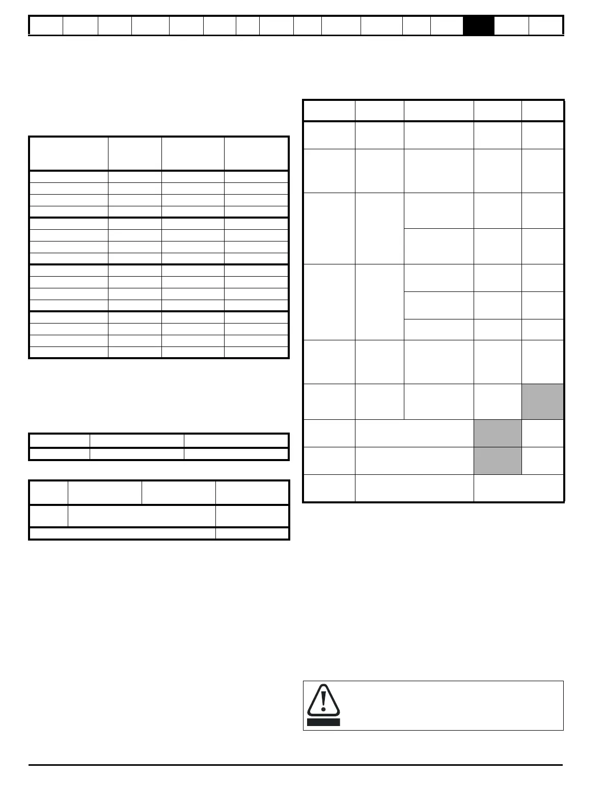
14.1.24 Braking resistor values
Table 14-34 Minimum resistance values and peak power rating for
the braking resistor at 40°C (104°F)
* Resistor tolerance: ±10%
** Continuous rating if drive is part of a common DC bus system. In
parallel systems without the DC bus connected, the resistors must be
matched to within ±5%.
14.1.25 Torque settings
Table 14-35 Master drive control and relay terminal data
Table 14-36 Drive power terminal data
14.1.26 Electromagnetic compatibility (EMC)
This is a summary of the EMC performance of the drive. For full details,
refer to the Unidrive SP EMC Data Sheet which can be obtained from
the supplier of the drive.
Table 14-37 Immunity compliance
1
See section Surge immunity of control circuits - long cables and
connections outside a building on page 86 for control ports for possible
requirements regarding grounding and external surge protection
Emission
The drive contains an in-built filter for basic emission control. An
additional optional external filter provides further reduction of emission.
The requirements of the following standards are met, depending on the
motor cable length and switching frequency.
Key (shown in decreasing order of permitted emission level):
E2R EN 61800-3 second environment, restricted distribution
(Additional measures may be required to prevent interference)
E2U EN 61800-3 second environment, unrestricted distribution
I Industrial generic standard EN 50081-2 (EN 61000-6-4)
EN 61800-3 first environment restricted distribution (The
following caution is required by EN 61800-3)
R Residential generic standard EN 50081-1 (EN 61000-6-3)
EN 61800-3 first environment unrestricted distribution
Model
Minimum
resistance*
Ω
Instantaneous
power rating**
kW
Average power
for 60s
kW
SPMA1401 5 122 122
SPMA1402 5 122 122
SPMA1601 10 125 113
SPMA1602 10 125 125
SPMD1201 2.5 61 61
SPMD1202 2.5 61 61
SPMD1203 1.9 80 80
SPMD1204 1.9 80 80
SPMD1401 5 122 122
SPMD1402 5 122 122
SPMD1403 3.8 160 160
SPMD1404 3.8 160 160
SPMD1601 10 125 113
SPMD1602 10 125 125
SPMD1603 6.2 202 165
SPMD1604 6.2 202 198
Model Connection type Torque setting
All Plug-in terminal block 0.5 N m 0.4 lb ft
Model AC terminals
High current DC
and braking
Ground terminal
All
M10 stud
15 N m
M10 stud
15 N m
Torque tolerance ±10%
Standard
Type of
immunity
Test specification Application Level
IEC61000-4-2
EN61000-4-2
Electrostatic
discharge
6kV contact
discharge
8kV air discharge
Module
enclosure
Level 3
(industrial)
IEC61000-4-3
EN61000-4-3
Radio
frequency
radiated field
10V/m prior to
modulation
80 - 1000MHz
80% AM (1kHz)
modulation
Module
enclosure
Level 3
(industrial)
IEC61000-4-4
EN61000-4-4
Fast transient
burst
5/50ns 2kV transient
at 5kHz repetition
frequency via
coupling clamp
Control lines
Level 4
(industrial
harsh)
5/50ns 2kV transient
at 5kHz repetition
frequency by direct
injection
Power lines
Level 3
(industrial)
IEC61000-4-5
EN61000-4-5
Surges
Common mode 4kV
1.2/50
μs waveshape
AC supply
lines:
line to ground
Level 4
Differential mode
2kV
1.2/50
μs waveshape
AC supply
lines:
line to line
Level 3
Lines to ground
Signal ports
to ground
1
Level 2
IEC61000-4-6
EN61000-4-6
Conducted
radio
frequency
10V prior to
modulation
0.15 - 80MHz
80% AM (1kHz)
modulation
Control and
power lines
Level 3
(industrial)
IEC61000-4-11
EN61000-4-11
Voltage dips
and
interruptions
-30% 10ms
+60% 100ms
-60% 1s
<-95% 5s
AC power
ports
EN50082-1
IEC61000-6-1
EN61000-6-1
Generic immunity standard for the
residential, commercial and light -
industrial environment
Complies
EN50082-2
IEC61000-6-2
EN61000-6-2
Generic immunity standard for the
industrial environment
Complies
EN61800-3
IEC61800-3
EN61800-3
Product standard for adjustable
speed power drive systems
(immunity requirements)
Meets immunity
requirements for first and
second environments
This is a product of the restricted distribution class according
to IEC 61800-3. In a residential environment this product may
cause radio interference in which case the user may be
required to take adequate measures.

 Loading...


