Safety
Information
Introduction
Product
Information
System
configuration
Mechanical
Installation
Electrical
Installation
Getting
Started
Basic
parameters
Running
the motor
Optimization
SMARTCARD
operation
Onboard
PLC
Advanced
parameters
Technical
Data
Diagnostics
UL Listing
Information
Unidrive SPM User Guide 85
Issue Number: 3 www.controltechniques.com
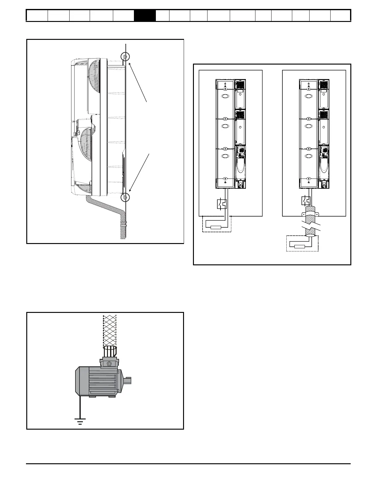
Ensure good EMC grounding.
Figure 6-26 Grounding the drive, motor cable shield and filter
Connect the shield of the motor cable to the ground terminal of the motor
frame using a link that is as short as possible and not exceeding 50mm
(2in) long. A full 360
°
termination of the shield to the terminal housing of
the motor is beneficial.
It is unimportant for EMC purposes whether the motor cable contains an
internal (safety) ground core, or there is a separate external ground
conductor, or grounding is through the shield alone. An internal ground
core will carry a high noise current and therefore it must be terminated
as close as possible to the shield termination.
Figure 6-27 Grounding the motor cable shield
Unshielded wiring to the optional braking resistor(s) may be used,
provided the wiring does not run external to the enclosure. Ensure a
minimum spacing of 300mm (12in) from signal wiring and the AC supply
wiring to the external EMC filter. Otherwise this wiring must be shielded.
Figure 6-28 Shielding requirements of optional external braking
resistor
Motor cable screen
(unbroken) physically
fixed to the backplate.
Ensure direct
metal contact
at drive and
filter (not shown)
mounting
points (any
paint must be
removed).
braking resistor
Enclosure
+DC BR
braking resistor
Enclosure

 Loading...


