Safety
Information
Introduction
Product
Information
System
configuration
Mechanical
Installation
Electrical
Installation
Getting
Started
Basic
parameters
Running
the motor
Optimization
SMARTCARD
operation
Onboard
PLC
Advanced
parameters
Technical
Data
Diagnostics
UL Listing
Information
126 Unidrive SPM User Guide
www.controltechniques.com Issue Number: 3
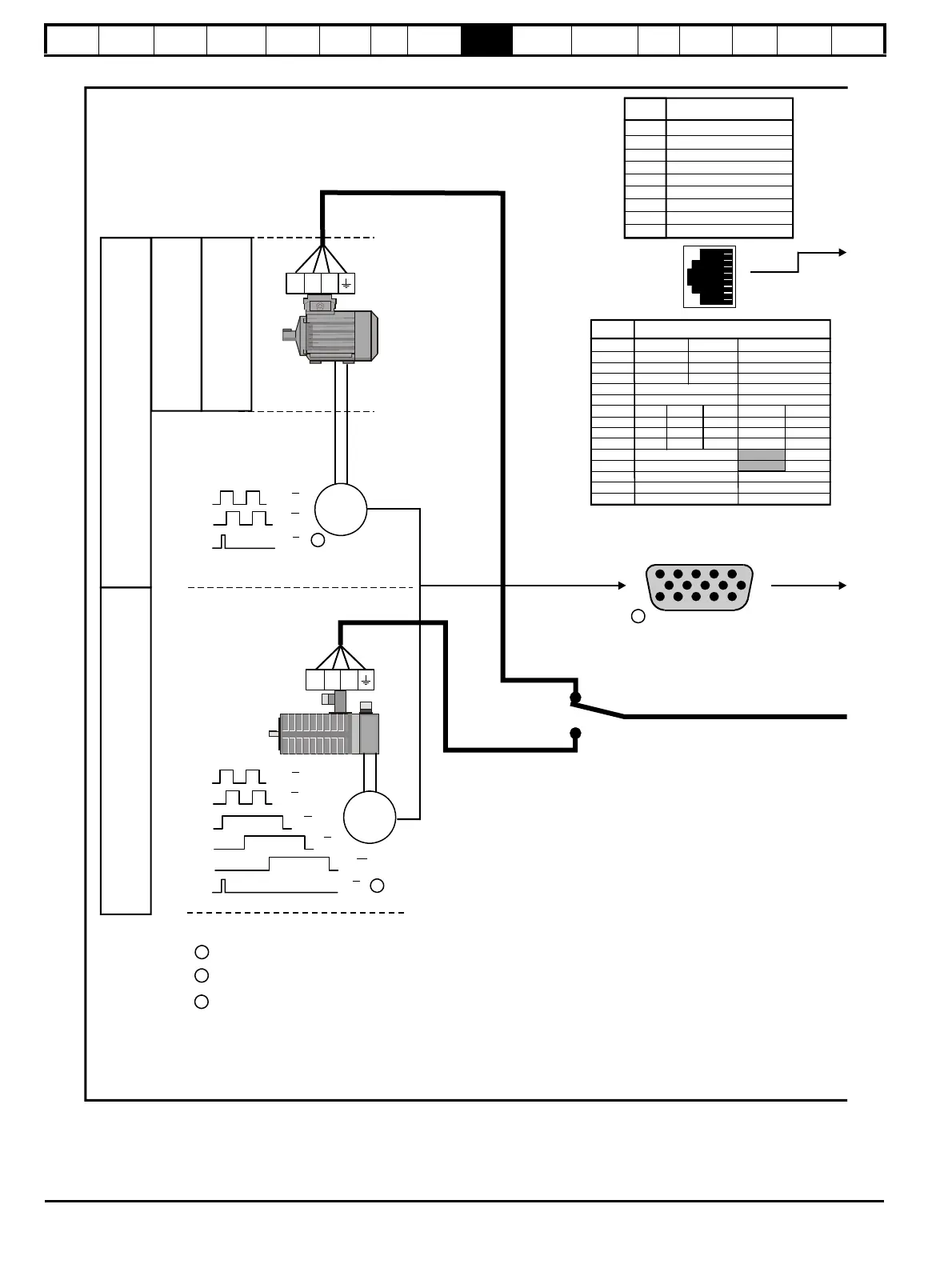
Figure 9-1 Minimum connections to get the motor running in any operating mode
E
A A
B B
U U
V V
W W
A A
B B
E
UVW
UVW
Z Z
Z Z
1
1
1
2
3
Marker pulse optional
Encoder screening connected to
Drive 0V open at encoder end
Thermal overload for braking resistor
to protect against fire risk. This must be
wired to interrupt the AC supply in the
event of a fault.
O
p
e
n
L
o
o
p
C
l
o
s
L
o
o
p
e
d
V
e
c
t
o
r
r
e
S
v
o
7 U Fout* Aout* Fout* Aout*
8 U\ Fout\* Aout\* Fout\* Aout\*
9 V Dout* Bout* Dout* Bout*
10 V\ Dout\* Bout\* Dout\* Bout\*
Servo motor
(permanent
magnet)
Serial
*Simulated encoder output only available in open-loop
2 RX TX
3 Isolated 0V
4 +24V
5 Isolated 0V
6 TX enable
7 RX\ TX\
8 RX\ TX\
Shell Isolated 0V
T15, the motor thermistor is common to Anip 3.
This input is set to Thermistor mode as default.
Set Pr to disable this trip
7.15
R
F
C

 Loading...


