Safety
Information
Introduction
Product
Information
System
configuration
Mechanical
Installation
Electrical
Installation
Getting
Started
Basic
parameters
Running
the motor
Optimization
SMARTCARD
operation
Onboard
PLC
Advanced
parameters
Technical
Data
Diagnostics
UL Listing
Information
Unidrive SPM User Guide 81
Issue Number: 3 www.controltechniques.com
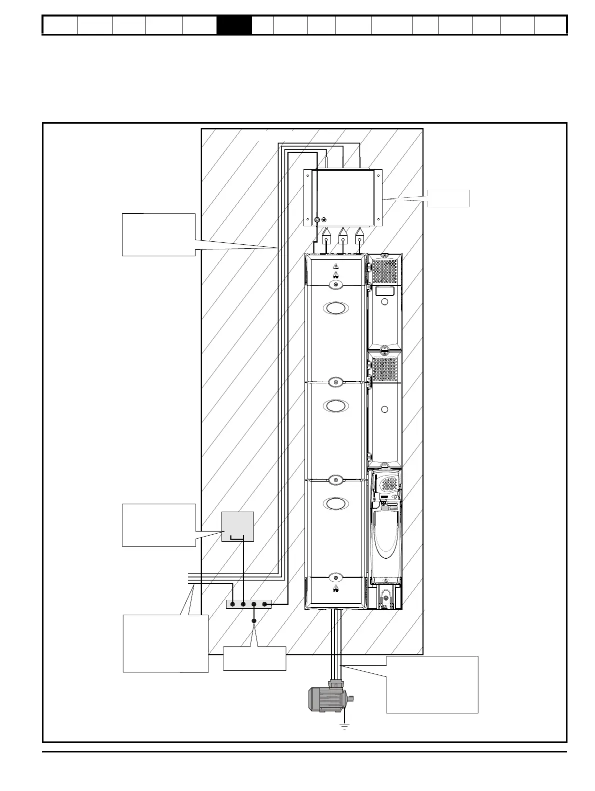
6.13.3 General requirements for EMC
Ground (earth) connections
The grounding arrangements should be in accordance with Figure 6-20, which shows a single drive on a back-plate with or without an additional
enclosure.
Figure 6-20 shows how to manage EMC when using an unshielded motor cable. However a shielded cable is preferable, in which case it should be
installed as shown in section 6.13.5 Compliance with generic emission standards on page 84.
Figure 6-20 General EMC enclosure layout showing ground connections
0V
If the control circuit 0V
is to be grounded, this
should be done at the
system controller only to
currents into the 0V circuit
Grounding bar
PE
~
PE
If ground connections are
made using a separate
cable, they should run
parallel to the appropriate
power cable to minimise
emissions
Use four core cable to
connect the motor to the drive.
The ground conductor in the
motor cable must be connected
directly to the earth terminal of
the drive and motor.
It must not be connected directly
to the power earth busbar.
The incoming supply ground
should be connected to a
single power ground bus bar
or low impedance earth
terminal inside the cubicle.
This should be used as a
common 'clean' ground for all
components inside the cubicle.
3 phase AC supply
Optional EMC
filter
Metal backplate

 Loading...


