Safety
Information
Introduction
Product
Information
System
configuration
Mechanical
Installation
Electrical
Installation
Getting
Started
Basic
parameters
Running
the motor
Optimization
SMARTCARD
operation
Onboard
PLC
Advanced
parameters
Technical
Data
Diagnostics
UL Listing
Information
146 Unidrive SPM User Guide
www.controltechniques.com Issue Number: 3
10.2 Maximum motor rated current
The maximum motor rated current allowed by the drive is greater than
the maximum Heavy Duty current rating in Pr 11.32. The ratio between
the Normal Duty rating and the Heavy Duty rating (Pr 11.32) varies
between drive sizes. The values for the Normal and Heavy Duty rating
can be found in section 3.2 Operating modes on page 17.
If the motor rated current (Pr 0.46) is set above the maximum Heavy
Duty current rating (Pr 11.32), the current limits and the motor thermal
protection scheme are modified (see section 10.3 Current limits and
section 10.4 Motor thermal protection , for more information).
10.3 Current limits
The default settings for the current limit parameters for Unidrive SPMA/D
are:
• 138.1% x motor rated current for open loop mode
• 165.7% x motor rated current for closed loop vector mode
• 150% x motor rated current for servo mode
There are three parameters which control the current limits:
• Motoring current limit: power flowing from the drive to the motor
• Regen current limit: power flowing from the motor to the drive
• Symmetrical current limit: current limit for both motoring and regen
operation
The lowest of either the motoring and regen current limit, or the
symmetrical current limit applies.
The maximum setting of these parameters depends on the values of
motor rated current, drive rated current and the power factor.
Increasing the motor rated current (Pr 0.46/5.07) above the Heavy Duty
rating (default value), will automatically reduce the current limits in
Pr 4.05 to Pr 4.07. If the motor rated current is then set to or below the
Heavy Duty rating, the current limits will be left at their reduced values.
The drive can be oversized to permit a higher current limit setting to
provide higher accelerating torque as required up to a maximum of
1000%.
10.4 Motor thermal protection
The drive models the temperature of the motor using the motor rated
current (Pr 5.07), the thermal time constant (Pr 4.15), whether low speed
thermal protection mode has been enabled (Pr 4.25) and the actual
current flowing at any point in time. Pr 4.19 gives the estimated motor
temperature as a percentage of maximum temperature.
The temperature of the motor (Pr 4.19) as a percentage of maximum
temperature, with a constant current magnitude of I, constant value of K
and constant value of Motor rated current (Pr 5.07) after time t is given
by:
Percentage motor temperature (Pr 4.19) = [I
2
/ (K x Motor rated
current)
2
] (1 - e
-t/τ
) x 100%
This assumes that the maximum allowed motor temperature is produced
by K x Motor rated current and that τ is the thermal time constant of the
point in the motor that reaches its maximum allowed temperature first. τ
is defined by Pr 4.15. If Pr 4.15 has a value between 0.0 and 1.0 the
thermal time constant is taken as 1.0.
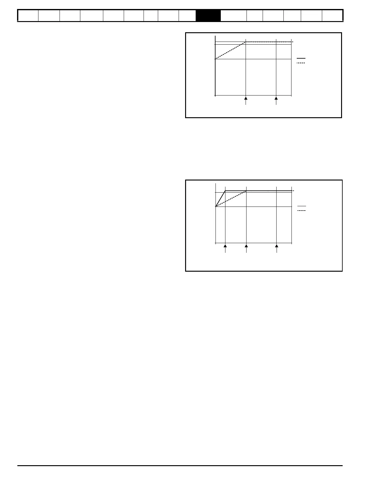
The value of K is defined as shown in Figure 10-1 and Figure 10-2.
For both Heavy and Normal duty ratings, Pr 4.25 can be used to select
two alternative protection characteristics.
Figure 10-1 Motor thermal protection (Heavy Duty)
If Pr 4.25 is 0 the characteristic is for a motor which can operate at rated
current over the whole speed range. Induction motors with this type of
characteristic normally have forced cooling. If Pr 4.25 is 1 the
characteristic is intended for motors where the cooling effect of motor
fan reduces with reduced motor speed below 50% of base speed/
frequency. The maximum value for K is 1.05, so that above the knee of
the characteristics the motor can operate continuously up to 105%
current.
Figure 10-2 Motor thermal protection (Normal Duty)
Both settings of Pr 4.25 are intended for motors where the cooling effect
of the motor fan reduces with reduced motor speed, but with different
speeds below which the cooling effect is reduced. If Pr 4.25 is 0 the
characteristic is intended for motors where the cooling effect reduces
with motor speed below 15% of base speed/frequency. If Pr 4.25 is 1 the
characteristic is intended for motors where the cooling effect reduces
with motor speed below 50% of base speed/frequency. The maximum
value for K is 1.01, so that above the knee of the characteristics the
motor can operate continuously up to 101% current.
When the estimated temperature in Pr 4.19 reaches 100% the drive
takes some action depending on the setting of Pr 4.16. If Pr 4.16 is 0, the
drive trips when Pr 4.19 reaches 100%. If Pr 4.16 is 1, the current limit is
reduced to (K - 0.05) x 100% when Pr 4.19 reaches 100%. The current
limit is set back to the user defined level when Pr 4.19 falls below 95%.
The thermal model temperature accumulator is reset to zero at power-up
and accumulates the temperature of the motor while the drive remains
powered-up. If the rated current defined by Pr 5.07 is altered, the
accumulator is reset to zero.
The default setting of the thermal time constant (Pr 4.15) is 89s for an
induction motor (open loop and closed loop vector), which is equivalent
to an overload of 150% for 60s from cold. The default value for a servo
motor is 20s, which is equivalent to an overload of 175% for 9s from
cold.
The time for the drive to trip from cold with constant motor current is
given by:
T
trip
= -(Pr 4.15) x ln(1 - (K x Pr 5.07 / Pr 4.01)
2
)
4.25
4.25
1.00
1.05
Base speed/
frequency
50% of base
speed/frequency
K
4.25
4.25
1.00
1.01
Base speed/
frequency
50% of
base speed/
frequency
15% of
base speed/
frequency
K

 Loading...


