Safety
Information
Introduction
Product
Information
System
configuration
Mechanical
Installation
Electrical
Installation
Getting
Started
Basic
parameters
Running
the motor
Optimization
SMARTCARD
operation
Onboard
PLC
Advanced
parameters
Technical
Data
Diagnostics
UL Listing
Information
Unidrive SPM User Guide 73
Issue Number: 3 www.controltechniques.com
6.6 Heatsink fan supply
The heatsink fan on Unidrive SPMA and SPMD requires an external
24Vdc supply. The connections for the heatsink fan supply must be made
to the upper terminal connector near to the W phase output on the drive.
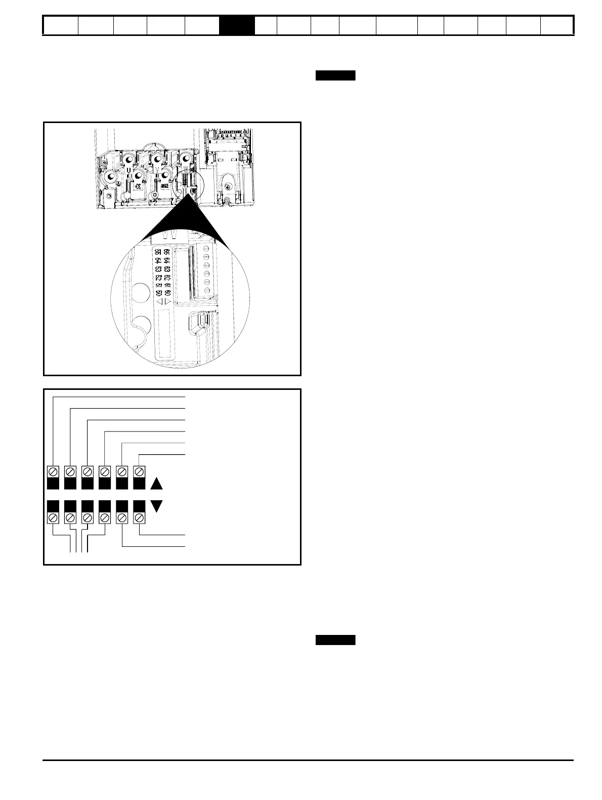
Figure 6-12 shows the position of the heatsink fan supply connections.
Figure 6-12 Location of the heatsink fan supply connections
(SPMA & SPMD)
Figure 6-13 Heatsink fan supply connections (SPMA & SPMD)
The heatsink fan supply requirements are as follows:
Nominal voltage: 24Vdc
Minimum voltage: 23.5Vdc
Maximum voltage: 27Vdc
Current drawn:
SPMA (all) 3.3A
SPMD12X1 to 12X4 3.3A
SPMD14X1 and 14X2 3.3A
SPMD14X3 and 14X4 4.5A
SPMD16X1 and 16X2 3.3A
SPMD16X3 and 16X4 4.5A
Recommended power supply: 24V, 5A
Recommended fuse:
SPMA (all) 4A fast blow (I
2
t <20A
2
s)
SPMD12X1 to 12X4 4A fast blow (I
2
t <20A
2
s)
SPMD14X1 and 14X2 4A fast blow (I
2
t <20A
2
s)
SPMD14X3 and 14X4 6.3A fast blow (I
2
t <100A
2
s)
SPMD16X1 and 16X2 4A fast blow (I
2
t <20A
2
s)
SPMD16X3 and 16X4 6.3A fast blow (I
2
t <100A
2
s)
The recommended wire gauge for the fan supply and low voltage mode
enable is 1mm
2
wire (16AWG).
For further information on the operation of the heatsink fan, refer to
section 5.9 Heatsink fan operation on page 54.
6.7 Control 24Vdc supply
The 24Vdc input on the Unidrive SPMA and SPMD has three main
functions.
• It can be used to supplement the drive’s own internal 24V when
multiple SM-Universal Encoder Plus, or SM-I/O Plus modules are
being used and the current drawn by these modules is greater than
the drive can supply. (If too much current is drawn from the drive, the
drive will initiate a 'PS.24V' trip)
• It can be used as a back-up power supply to keep the control circuits
of the drive powered up when the line power supply is removed. This
allows any fieldbus modules, application modules, encoders or serial
communications to continue to operate.
• It can be used to commission the drive when line power voltages are
not available, as the display operates correctly. However, the drive
will be in the UV trip state unless either line power or low voltage DC
operation is enabled, therefore diagnostics may not be possible.
(Power down save parameters are not saved when using the 24V
back-up power supply input.)
The working voltage range of the 24V power supply is as follows:
Maximum continuous operating voltage: 30.0 V
Minimum continuous operating voltage: 19.2 V
Nominal operating voltage: 24.0 V
Minimum start up voltage: 21.6 V
Maximum power supply requirement at 24V: 60 W
Recommended fuse: 3 A, 50 Vdc
Minimum and maximum voltage values include ripple and noise. Ripple
and noise values must not exceed 5%.
6.8 Low voltage DC power supply
The Unidrive SPMA and SPMD can be operated from low voltage DC
supplies, nominally 24Vdc (control) and 48Vdc (power). The low voltage
DC power operating mode is designed either, to allow for motor
operation in an emergency back-up situation following failure of the AC
supply, for example in elevators; or to limit the speed of a servo motor
during commissioning/start-up of equipment, for example a robot cell.
The working voltage range of the low voltage DC power supply is as follows:
Unidrive SPMD (200V drives)
Minimum continuous operating voltage: 36V
Nominal continuous operating voltage: 48 to 72V
Maximum braking IGBT turn on voltage: 95.4V
Maximum over voltage trip threshold: 104.4V
Unidrive SPMA and SPMD (400V and 690V drives)
Minimum continuous operating voltage: 36V
Nominal continuous operating voltage: 48 to 96V
Maximum braking IGBT turn on voltage: 127.2V
Maximum over voltage trip threshold: 139.2V
N
The nominal low voltage supply level is set by the user in Pr 6.46.
The default setting is 48V for all drive sizes.
The over voltage trip threshold and braking IGBT turn on voltage are
scaled from this value as follows:
Brake IGBT turn on = 1.325 x Pr 6.46 (V)
Over voltage trip = 1.45 x Pr 6.46 (V)
For application data, refer to the Unidrive SP Low Voltage DC Installation
Guide.
55 54 53 52 51 50
65 64 63 62 61 60
To the heatsink fan
0V
24V low voltage DC mode enable
0V
24V heatsink fan supply
Upper terminal connector
Lower terminal connector
0V
0V
Rectifier status 1 input
Rectifier status 0 input

 Loading...


