Safety
Information
Introduction
Product
Information
System
configuration
Mechanical
Installation
Electrical
Installation
Getting
Started
Basic
parameters
Running
the motor
Optimization
SMARTCARD
operation
Onboard
PLC
Advanced
parameters
Technical
Data
Diagnostics
UL Listing
Information
8 Unidrive SPM User Guide
www.controltechniques.com Issue Number: 3
2 Introduction
The Unidrive Solutions Platform Modular drive offers the possibility of
implementing many custom power systems with a wide range of power
modules. The power range is 45kW to 1.9MW and the modular design of
input and output stages enables a wide range of very compact and
efficient systems to be realized. These include:
• Parallel output stages for higher power motors:
Up to a maximum of 10 SPMA/D modules
(1 master module with up to 9 slave modules, OR
1 remote mounted control master pod controlling up to 10
slaves. This allows the user to place all circuitry in one low
voltage cabinet)
• Common DC bus multi-drive systems for:
Connection to larger existing power supplies
Energy sharing between motoring and regenerating drives
• Active front end drive systems for:
Minimising supply current harmonics
Four quadrant motor control
• Multiple controlled rectifier bridges (SPMC) for:
Minimising supply current harmonics by drawing 6, 12 or 18
pulse supply load currents
• Uncontrolled rectifier bridges (SPMU) for use in applications with
poor quality power supplies, very long motor cables and where DC
bus pre-charge is done by other means
2.1 Rectifier (SPMC/U)
There are two distinct types of rectifier available
SPMC: Controlled SCR/thyristor rectifier
SPMU: Uncontrolled diode rectifier
Different current and voltage ratings are available for both types.
The Unidrive SPMC is a half controlled SCR/thyristor bridge and is used
as a front end to the SPMD inverter module or as a stand alone rectifier
for several smaller drives. Soft-start is built in.
The Unidrive SPMU is used as a front end to the SPMD inverter module
or as a stand alone rectifier for several smaller drives. Softstart must be
supplied externally using a resistor and contactor or SPMC.
An external 24V, 3A power supply is required in addition to the AC
supply to allow the rectifier to operate. See section 6.14.3 Unidrive
SPMC/U control connections on page 89 and section 14.1.4 Unidrive
SPM 24V power supply on page 267. Control wiring is required between
the rectifier and motoring drive(s) so that if the rectifier indicates a fault
the motoring drive(s) will be disabled.
The 24V supply must be protected using a 4A slow-blow fuse, one for
each supply pole.
Control connections to the Unidrive SPMC/U should be made with
0.5mm
2
cable.
The status relay contacts are rated for switching non-inductive loads at
250Vac 6A non-inductive, up to 4Adc if the voltage is limited to 40V or up
to 400mA dc if the voltage is limited to 250Vdc. Protection from
overcurrent must be provided.
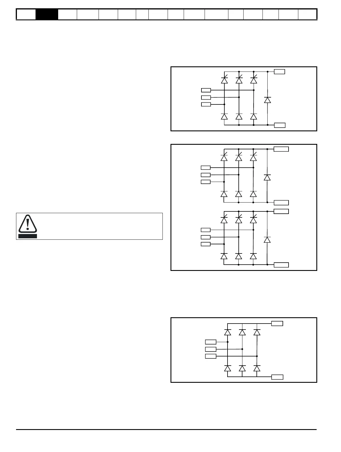
2.1.1 Half controlled SCR/thyristor rectifier (SPMC)
The half controlled SCR/thyristor bridge is used as a front end to the
SPMD inverter module or as a stand alone rectifier for several smaller
drives. Control wiring is linked to the inverter for trip monitoring. Soft-
start is built in.
SPMC14X2 and 16X1
Figure 2-1 Single half controlled SCR/thyristor
SPMC2X0X
Figure 2-2 Dual half controlled SCR/thyristor
2.1.2 Diode rectifier (SPMU)
The uncontrolled diode rectifier is supplied as an alternative to the half
controlled SCR/thyristor rectifier. Control wiring is limited to a thermal
trip. Soft-start is achieved by the use of an external contactor and
resistor.
SPMU14X2 and 16X1
Figure 2-3 Single diode rectifier
A separate input line reactor (INLXXX) of at least the value
shown in Table 6-2 and Table 6-3 on page 68 must be used
with the rectifiers. Failure to provide sufficient reactance could
damage or reduce the service life of the rectifier or inverter.

 Loading...


