Safety
Information
Introduction
Product
Information
System
configuration
Mechanical
Installation
Electrical
Installation
Getting
Started
Basic
parameters
Running
the motor
Optimization
SMARTCARD
operation
Onboard
PLC
Advanced
parameters
Technical
Data
Diagnostics
UL Listing
Information
188 Unidrive SPM User Guide
www.controltechniques.com Issue Number: 3
*For more information, refer to section 13.21.5 Stop modes on
page 257.
**For more information, refer to section 13.21.6 Line power supply loss
modes on page 258.
***For more information, refer to section 13.21.7 Start / stop logic
modes on page 259.
****For more information, refer to section 13.21.8 Catch a spinning
motor on page 260.
*****The drive thermal model system normally controls the fan speed,
however the fan can be forced to operate at full speed if this parameter
is set to 1. When this is set to 1 the fan remains at full speed until 10s
after this parameter is set to zero. Note that the fan willl only run at full
speed if the drive is not in a UU condition.
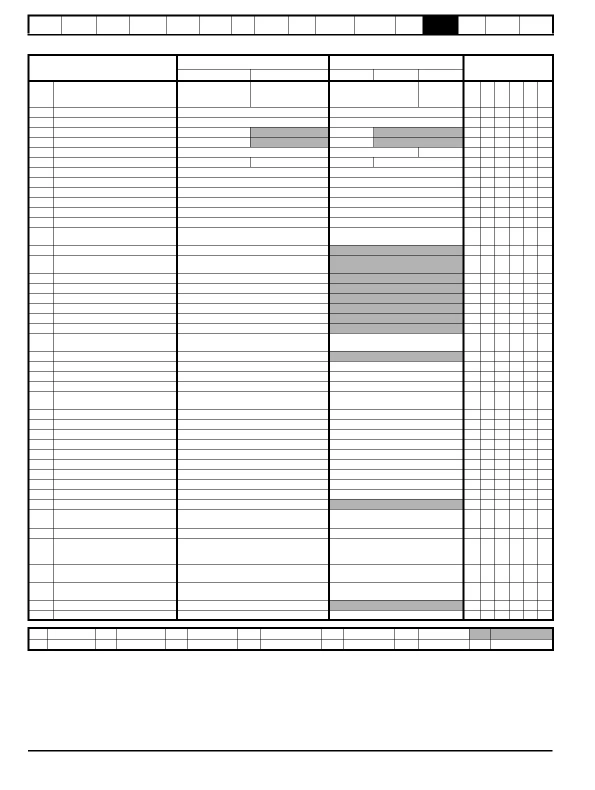
Parameter
Range(
Ú) Default(Ö)
Type
OL CL OL VT SV
6.01 Stop mode
COASt (0), rP (1),
rP.dcl (2), dcl (3),
td.dcl (4), diSAbLE (5)
COASt (0), rP (1),
no.rP (2)
rP (1)
no.rP (2)
RW Txt US
6.03 Line power supply loss mode diS (0), StoP (1), ridE.th (2) diS (0) RW Txt US
6.04 Start / stop logic select 0 to 4 4 RW Uni US
6.06 Injection braking level 0 to 150.0%
100.0% RW Uni RA US
6.07 Injection braking time 0.0 to 25.0s
1.0 RW Uni US
6.08 Hold zero speed OFF (0) or On (1) OFF (0) On (1) RW Bit US
6.09 Catch a spinning motor {0.33} 0 to 3 0 to 1 0 1 RW Uni US
6.12 Enable stop key OFF (0) or On (1) OFF (0) RW Bit US
6.13 Enable forward / reverse key {0.28} OFF (0) or On (1) OFF (0) RW Bit US
6.15 Drive enable OFF (0) or On (1) On (1) RW Bit US
6.16 Electricity cost per kWh 0.0 to 600.0 currency units per kWh 0 RW Uni US
6.17 Reset energy meter OFF (0) or On (1) OFF (0) RW Bit NC
6.18 Time between filter changes 0 to 30,000 hrs 0 RW Uni US
6.19
Filter change required /
change done
OFF (0) or On (1) OFF (0) RW Bit PT
6.20 Powered-up time: years.days 0 to 9.364 years.days
RW Uni NC PT
6.21
Powered-up time:
hours.minutes
0 to 23.59 hours.minutes
RW Uni NC PT
6.22 Run time: years.days 0 to 9.364 years.days
RO Uni NC PT PS
6.23 Run time: hours.minutes 0 to 23.59 hours.minutes
RO Uni NC PT PS
6.24 Energy meter: MWh ±999.9 MWh
RO Bi NC PT PS
6.25 Energy meter: kWh ±99.99 kWh
RO Bi NC PT PS
6.26 Running cost ±32,000
RO Bi NC PT
6.27 Time before filter change due 0 to 30,000 hrs
RO Uni NC PT PS
6.28
Select clock for trip log time
sampling
OFF (0) or On (1) OFF (0) RW Bit US
6.29 Hardware enable OFF (0) or On (1) RO Bit NC PT
6.30 Sequencing bit: Run forward OFF (0) or On (1) OFF (0) RW Bit NC
6.31 Sequencing bit: Jog forward OFF (0) or On (1) OFF (0) RW Bit NC
6.32 Sequencing bit: Run reverse OFF (0) or On (1) OFF (0) RW Bit NC
6.33
Sequencing bit: Forward /
reverse
OFF (0) or On (1) OFF (0) RW Bit NC
6.34 Sequencing bit: Run OFF (0) or On (1) OFF (0) RW Bit NC
6.35 Forward limit switch OFF (0) or On (1) OFF (0) RW Bit NC
6.36 Reverse limit switch OFF (0) or On (1) OFF (0) RW Bit NC
6.37 Sequencing bit: Jog reverse OFF (0) or On (1) OFF (0) RW Bit NC
6.39 Sequencing bit: Not stop OFF (0) or On (1) OFF (0) RW Bit NC
6.40 Enable sequencer latching OFF (0) or On (1) OFF (0) RW Bit US
6.41 Drive event flags 0 to 65,535 0 RW Uni NC
6.42 Control word 0 to 32,767 0 RW Uni NC
6.43 Control word enable OFF (0) or On (1) OFF (0) RW Bit US
6.44 Active supply OFF (0) or On (1)
RO Bit NC PT
6.45
Force cooling fan to run at full
speed
*****
OFF (0) or On (1) OFF (0) RW Bit US
6.46 Nominal low voltage supply 48V to 96V 48 RW Uni PT US
6.47
Disable line power supply /
phase loss detection from
input rectifier
OFF (0) or On (1) OFF (0) RW Bit US
6.48
Line powersupply loss ride
through detection level
0 to DC_VOLTAGE_SET_MAX V
200V drive: 205, 400V drive: 410,
575V drive: 540, 690V drive: 540
RW Uni RA US
6.49
Disable multi-module drive
module number storing on trip
OFF (0) or On (1) OFF (0) RW Bit US
6.50 Drive comms state drv (0), SLot 1(1), SLot 2 (2), SLot 3 (3)
RO Txt NC PT
6.51 External rectifier not active OFF (0) or On (1) OFF (0) RW Bit
RW Read / Write RO Read only Uni Unipolar Bi Bi-polar Bit Bit parameter Txt Text string
FI Filtered DE Destination NC Not copied RA Rating dependent PT Protected US User save PS Power down save

 Loading...


