Safety
Information
Introduction
Product
Information
System
configuration
Mechanical
Installation
Electrical
Installation
Getting
Started
Basic
parameters
Running
the motor
Optimization
SMARTCARD
operation
Onboard
PLC
Advanced
parameters
Technical
Data
Diagnostics
UL Listing
Information
194 Unidrive SPM User Guide
www.controltechniques.com Issue Number: 3
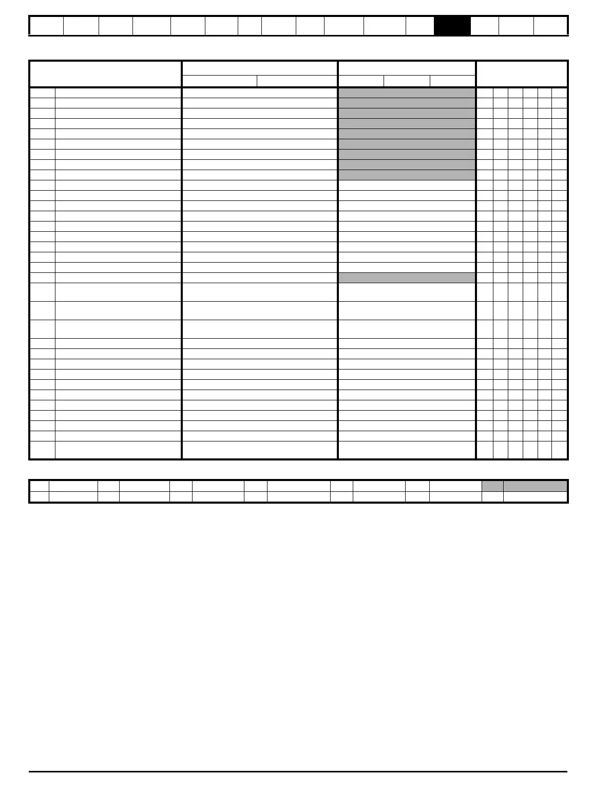
Parameter
Range(
Ú) Default(Ö)
Type
OL CL OL VT SV
8.01 T24 digital I/O 1 state OFF (0) or On (1)
RO Bit NC PT
8.02 T25 digital I/O 2 state OFF (0) or On (1)
RO Bit NC PT
8.03 T26 digital I/O 3 state OFF (0) or On (1)
RO Bit NC PT
8.04 T27 digital input 4 state OFF (0) or On (1)
RO Bit NC PT
8.05 T28 digital input 5 state OFF (0) or On (1)
RO Bit NC PT
8.06 T29 digital input 6 state OFF (0) or On (1)
RO Bit NC PT
8.07 Relay state OFF (0) or On (1)
RO Bit NC PT
8.08 T22 24V output state OFF (0) or On (1)
RO Bit NC PT
8.09 Drive enable indicator OFF (0) or On (1)
RO Bit NC PT
8.10 Drive enable mode select OFF (0) or On (1) OFF (0) RW Bit US
8.11 T24 digital I/O 1 invert OFF (0) or On (1) OFF (0) RW Bit US
8.12 T25 digital I/O 2 invert OFF (0) or On (1) OFF (0) RW Bit US
8.13 T26 digital I/O 3 invert OFF (0) or On (1) OFF (0) RW Bit US
8.14 T27 digital input 4 invert OFF (0) or On (1) OFF (0) RW Bit US
8.15 T28 digital input 5 invert OFF (0) or On (1) OFF (0) RW Bit US
8.16 T29 digital input 6 invert OFF (0) or On (1) OFF (0) RW Bit US
8.17 Relay source invert OFF (0) or On (1) OFF (0) RW Bit US
8.18 T22 24V output source invert OFF (0) or On (1) On (1) RW Bit US
8.20 Digital I/O read word 0 to 511
RO Uni NC PT
8.21
T24 digital I/O 1 source/
destination
Pr 0.00 to 21.51 Pr 10.03 RW Uni DE PT US
8.22
T25 digital I/O 2 source/
destination
Pr 0.00 to 21.51 Pr 10.33 RW Uni DE PT US
8.23
T26 digital I/O 3 source/
destination
Pr 0.00 to 21.51 Pr 6.30 RW Uni DE PT US
8.24 T27 digital input 4 destination Pr 0.00 to 21.51 Pr 6.32 RW Uni DE PT US
8.25 T28 digital input 5 destination Pr 0.00 to 21.51 Pr 1.41 RW Uni DE PT US
8.26 T29 digital input 6 destination {0.17}Pr 0.00 to 21.51 Pr 6.31 RW Uni DE PT US
8.27 Relay source Pr 0.00 to 21.51 Pr 10.01 RW Uni PT US
8.28 T22 24V output source Pr 0.00 to 21.51 Pr 0.00 RW Uni PT US
8.29 Positive logic select {0.18} OFF (0) or On (1) On (1) RW Bit PT US
8.30 Open collector output OFF (0) or On (1) OFF (0) RW Bit US
8.31 T24 digital I/O 1 output select OFF (0) or On (1) On (1) RW Bit US
8.32 T25 digital I/O 2 output select OFF (0) or On (1) OFF (0) RW Bit US
8.33 T26 digital I/O 3 output select OFF (0) or On (1) OFF (0) RW Bit US
8.39
T28 & T29 digital input auto-
selection disable
{0.16} OFF (0) or On (1) OFF (0) RW Bit US
RW Read / Write RO Read only Uni Unipolar Bi Bi-polar Bit Bit parameter Txt Text string
FI Filtered DE Destination NC Not copied RA Rating dependent PT Protected US User save PS Power down save
 Loading...


