Safety
Information
Introduction
Product
Information
System
configuration
Mechanical
Installation
Electrical
Installation
Getting
Started
Basic
parameters
Running
the motor
Optimization
SMARTCARD
operation
Onboard
PLC
Advanced
parameters
Technical
Data
Diagnostics
UL Listing
Information
204 Unidrive SPM User Guide
www.controltechniques.com Issue Number: 3
The control terminal relay can be selected as an output to release a brake. If a drive is set up in this manner and a drive replacement takes
place, prior to programming the drive on initial power up, the brake may be released.
When drive terminals are programmed to non default settings the result of incorrect or delayed programming must be considered. The use of
a Smartcard in boot mode or an SM-Applications module can ensure drive parameters are immediately programmed to avoid this situation.
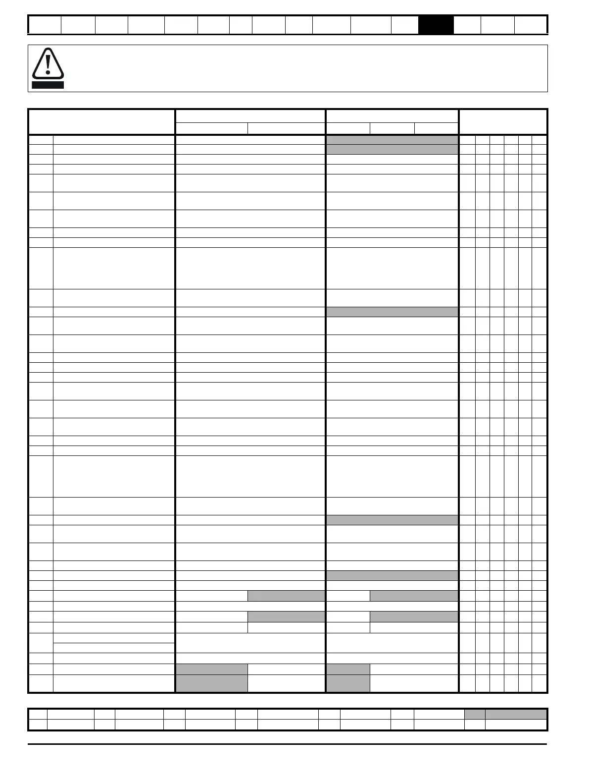
Parameter
Range(
Ú) Default(Ö)
Type
OL CL OL VT SV
12.01 Threshold detector 1 output OFF (0) or On (1)
RO Bit NC PT
12.02 Threshold detector 2 output OFF (0) or On (1)
RO Bit NC PT
12.03 Threshold detector 1 source Pr 0.00 to 21.51 Pr 0.00 RW Uni PT US
12.04 Threshold detector 1 level 0.00 to 100.00 % 0.00 RW Uni US
12.05
Threshold detector 1
hysteresis
0.00 to 25.00 % 0.00 RW Uni US
12.06
Threshold detector 1 output
invert
OFF (0) or On (1) OFF (0) RW Bit US
12.07
Threshold detector 1
destination
Pr 0.00 to 21.51 Pr 0.00 RW Uni DE PT US
12.08 Variable selector 1 source 1 Pr 0.00 to 21.51 Pr 0.00 RW Uni PT US
12.09 Variable selector 1 source 2 Pr 0.00 to 21.51 Pr 0.00 RW Uni PT US
12.10 Variable selector 1 mode
Select input 1 (0), select input 2 (1), add (2),
subtract (3), multiply (4), divide (5),
time constant (6), linear ramp (7), modulus (8),
powers (9), sectional control (10),
external rectifier monitor (11)
Select input 1 (0) RW Uni US
12.11
Variable selector 1
destination
Pr 0.00 to 21.51 Pr 0.00 RW Uni DE PT US
12.12 Variable selector 1 output ±100.00 %
RO Bi NC PT
12.13
Variable selector 1 source 1
scaling
±4.000 1.000 RW Bi US
12.14
Variable selector 1 source 2
scaling
±4.000 1.000 RW Bi US
12.15 Variable selector 1 control 0.00 to 100.00 s 0.00 RW Uni US
12.23 Threshold detector 2 source Pr 0.00 to 21.51 Pr 0.00 RW Uni PT US
12.24 Threshold detector 2 level 0.00 to 100.00 % 0.00 RW Uni US
12.25
Threshold detector 2
hysteresis
0.00 to 25.00 % 0.00 RW Uni US
12.26
Threshold detector 2 output
invert
OFF (0) or On (1) OFF (0) RW Bit US
12.27
Threshold detector 2
destination
Pr 0.00 to 21.51 Pr 0.00 RW Uni DE PT US
12.28 Variable selector 2 source 1 Pr 0.00 to 21.51 Pr 0.00 RW Uni PT US
12.29 Variable selector 2 source 2 Pr 0.00 to 21.51 Pr 0.00 RW Uni PT US
12.30 Variable selector 2 mode
Select input 1 (0), select input 2 (1), add (2),
subtract (3), multiply (4), divide (5),
time constant (6), linear ramp (7), modulus (8),
powers (9), sectional control (10),
external rectifier monitor (11)
Select input 1 (0) RW Uni US
12.31
Variable selector 2
destination
Pr 0.00 to 21.51 Pr 0.00 RW Uni DE PT US
12.32 Variable selector 2 output ±100.00 %
RO Bi NC PT
12.33
Variable selector 2 source 1
scaling
±4.000 1.000 RW Bi US
12.34
Variable selector 2 source 2
scaling
±4.000 1.000 RW Bi US
12.35 Variable selector 2 control 0.00 to 100.00 s 0.00 RW Uni US
12.40 Brake release indicator OFF (0) or On (1)
RO Bit NC PT
12.41 Brake controller enable dis (0), rEL (1), d IO (2), USEr (3) dis (0) RW Txt US
12.42 Upper current threshold 0 to 200 %
50 RW Uni US
12.43 Lower current threshold 0 to 200 % 10 RW Uni US
12.44 Brake release frequency 0.0 to 20.0 Hz
1.0 RW Uni US
12.45 Brake apply frequency / speed 0.0 to 20.0 Hz 0 to 200 rpm 2.0
5
RW Bit US
12.46
OL> Pre-brake release delay
0.0 to 25.0 s 1.0 RW Uni US
CL> Brake apply speed delay
12.47 Post brake release delay 0.0 to 25.0 s
1.0
RW Uni US
12.48 Brake apply delay
0.0 to 25.0 s
1.0
RW Uni US
12.49
Enable position controller
during brake release
OFF (0) or On (1)
OFF (0)
RW Bit US
RW Read / Write RO Read only Uni Unipolar Bi Bi-polar Bit Bit parameter Txt Text string
FI Filtered DE Destination NC Not copied RA Rating dependent PT Protected US User save PS Power down save
 Loading...


