Safety
Information
Introduction
Product
Information
System
configuration
Mechanical
Installation
Electrical
Installation
Getting
Started
Basic
parameters
Running
the motor
Optimization
SMARTCARD
operation
Onboard
PLC
Advanced
parameters
Technical
Data
Diagnostics
UL Listing
Information
Unidrive SPM User Guide 221
Issue Number: 3 www.controltechniques.com
SM-Resolver parameters
*See trip SLX.Er, Feedback module category on page 284.
0.XX
0.XX
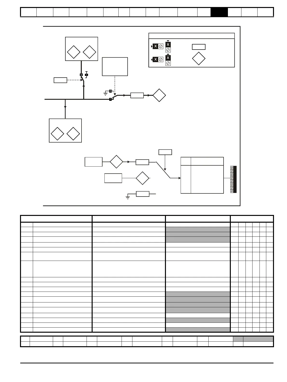
Key
Read-write (RW)
parameter
Read-only (RO)
parameter
Input
terminals
Output
terminals
The parameters are all shown at their default settings
x.04 x.05
Position
Revolution
counter
Positional information
x.29 x.30
Position
Revolution
counter
Non marker reset
positional information
x.25
Ratio
numerator
Encoder
source
Resolver
source
x.49
Lock position
feedback
Resolver
selected as
drive feedback
(Pr )
3.26
x.03
x.19
Feedback
filter
Speed
feedback
Parameter
Range(
Ú) Default(Ö)
Type
x.01 Solutions Module ID 0 to 599 101 RO Uni PT US
x.03 Speed ±40,000.0 rpm
RO Bi FI NC PT
x.04 Revolution counter 0 to 65,535 revolutions
RO Uni FI NC PT
x.05 Position
0 to 65,535 1/2
16
ths of a revolution
RO Uni FI NC PT
x.10 Equivalent lines per revolution 0 to 50,000 4096 RW Uni US
x.13 Resolver excitation 3:1 (0), 2:1 (1 or 2) 3:1 (0) RW Uni US
x.15 Resolver poles
2 pole (0), 4 pole (1), 6 pole (2),
8 pole (3 to 11)
2 pole (0) RW Uni US
x.17 Error detection level
Bit 0 (LSB) = Wire break detect
Bit 1 = Phase error detect
Bit 2 (MSB) = SSI power supply bit monitor
Value is binary sum
1RWUniUS
x.19 Feedback filter 0 (0), 1 (1), 2 (2), 4 (3), 8 (4), 16 (5) ms 0 RW Txt US
x.24 Encoder simulation source Pr 0.00 to Pr 21.51 Pr 0.00 RW Uni PT US
x.25 Encoder simulation ratio numerator 0.0000 to 3.0000 0.25 RW Uni US
x.29 Non-marker reset revolution counter 0 to 65,535 revolutions
RO Uni NC PT
x.30 Non-marker reset position
0 to 65,535 1/2
16
ths of a revolution
RO Uni NC PT
x.35 Freeze revolution counter 0 to 65,535 revolutions
RO Uni NC PT
x.36 Freeze position
0 to 65,535 1/2
16
ths of a revolution
RO Uni NC PT
x.39 Freeze flag OFF (0) or On (1) OFF (0) RW Bit NC
x.45 Position feedback initialised OFF (0) or On (1)
RO Bit NC PT
x.49 Lock position feedback OFF (0) or On (1) OFF (0) RW Bit NC
x.50 Solutions Module error status* 0 to 255
RO Uni NC PT
RW Read / Write RO Read only Uni Unipolar Bi Bi-polar Bit Bit parameter Txt Text string
FI Filtered DE Destination NC Not copied RA Rating dependent PT Protected US User save PS Power down save

 Loading...


