Safety
Information
Introduction
Product
Information
System
configuration
Mechanical
Installation
Electrical
Installation
Getting
Started
Basic
parameters
Running
the motor
Optimization
SMARTCARD
operation
Onboard
PLC
Advanced
parameters
Technical
Data
Diagnostics
UL Listing
Information
256 Unidrive SPM User Guide
www.controltechniques.com Issue Number: 3
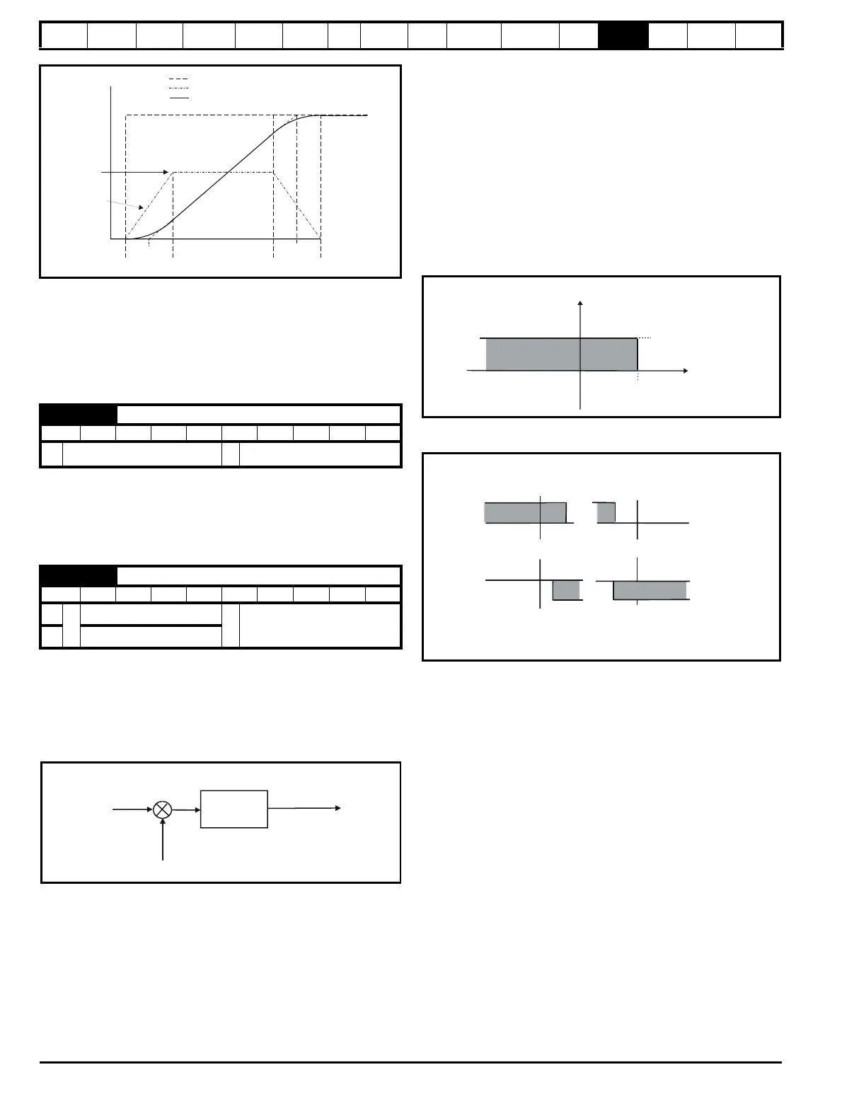
Since the ramp rate is defined in s/100Hz or s/1000rpm and the S ramp
parameter is defined in s
2
/100Hz or s
2
/1000rpm, the time T for the
'curved' part of the S can be determined from:
T = S ramp rate of change / Ramp rate
Enabling S ramp increases the total ramp time by the period T since an
additional T/2 is added to each end of the ramp in producing the S.
13.21.4 Torque modes
Parameter for main torque reference. The normal update rate for the
torque reference is 4ms. However if analog inputs 2 or 3 on the drive are
used as the source of the reference, the drive is in closed-loop vector or
servo mode and the analog inputs are in voltage mode with zero offset,
the sample time is reduced to 250μs.
Open loop
If this parameter is 0 normal frequency control is used. If this parameter
is set to 1 the current demand is connected to the current PI controller
giving closed loop torque/current demand as shown below. The current
error is passed through proportional and integral terms to give a
frequency reference which is limited to the range: -SPEED_FREQ_MAX
to +SPEED_FREQ_MAX.
Closed loop vector and Servo
When this parameter is set to 1, 2 or 3 the ramps are not active while the
drive is in the run state. When the drive is taken out of the run state, but
not disabled, the appropriate stopping mode is used. It is recommended
that coast stopping or stopping without ramps are used. However, if
ramp stop mode is used the ramp output is pre-loaded with the actual
speed at the changeover point to avoid unwanted jumps in the speed
reference.
0: Speed control mode
The torque demand is equal to the speed loop output.
1: Torque control
The torque demand is given by the sum of the torque reference and
the torque offset, if enabled. The speed is not limited in any way,
however, the drive will trip at the overspeed threshold if runaway
occurs.
2: Torque control with speed override
The output of the speed loop defines the torque demand, but is
limited between 0 and the resultant torque reference (Pr 4.08 and Pr
4.09 (if enabled)). The effect is to produce an operating area as
shown below if the final speed demand and the resultant torque
reference are both positive. The speed controller will try and
accelerate the machine to the final speed demand level with a
torque demand defined by the resultant torque reference. However,
the speed cannot exceed the reference because the required torque
would be negative, and so it would be clamped to zero.
Depending on the sign of the final speed demand and the resultant
torque the four areas of operation shown below are possible.
This mode of operation can be used where torque control is required, but
the maximum speed must be limited by the drive.
3: Coiler/uncoiler mode
Positive final speed demand:
A positive resultant torque will give torque control with a positive
speed limit defined by the final speed demand. A negative resultant
torque will give torque control with a negative speed limit of -5rpm.
Negative final speed demand:
A negative resultant torque will give torque control with a negative
speed limit defined by the final speed demand. A positive resultant
torque will give torque control with a positive speed limit of +5rpm.
Example of coiler operation:
This is an example of a coiler operating in the positive direction. The final
speed demand is set to a positive value just above the coiler reference
speed. If the resultant torque demand is positive the coiler operates with
a limited speed, so that if the material breaks the speed does not exceed
a level just above the reference. It is also possible to decelerate the
coiler with a negative resultant torque demand. The coiler will decelerate
down to -5rpm until a stop is applied. The operating area is shown in the
following diagram.
4.08 Torque reference
RW Bi US
Ú
±USER_CURRENT_MAX %
Ö
0.00
4.11 Torque mode selector
RW Uni US
OL
Ú
0 to 1
Ö
0
CL 0 to 4
t
Acceleration
Actual Speed
Programmed
ramp rate
TT
T/2 T/2 T/2T/2
S ramp
acceleration
ramp
Demanded Speed
P Pr
4.13
I Pr
4.14
Current
demand
Active
current
Frequency
reference
+
-
4.08
Pr (if enabled)
4.09
Pr
3.01
Speed
Current
+ final speed demand
+ resultant torque
- final speed demand
+ resultant torque
+ final speed demand
-resultant torque
- final speed demand
- resultant torque
 Loading...


