Safety
Information
Introduction
Product
Information
System
configuration
Mechanical
Installation
Electrical
Installation
Getting
Started
Basic
parameters
Running
the motor
Optimization
SMARTCARD
operation
Onboard
PLC
Advanced
parameters
Technical
Data
Diagnostics
UL Listing
Information
Unidrive SPM User Guide 259
Issue Number: 3 www.controltechniques.com
weakening begins. These oscillations can be reduced by increasing
the proportional gain. A system has been included to prevent
regulation because of the opposite actions of the ramps and the
current limit. This can reduce the actual level that the current limit
becomes active by 12.5%. This still allows the current to increase up
to the current limit set by the user. However the current limit flag
(Pr 10.09) could become active up to 12.5% below the current limit
depending on the ramp rate used.
Torque control:
Again the controller will normally operate with an integral term only,
particularly below the point where field weakening begins. The first
signs of instability will appear around base speed, and can be
reduced by increasing the proportional gain. The controller can be
less stable in torque control mode rather than when it is used for
current limiting. This is because load helps to stabilise the controller,
and under torque control the drive may operate with light load.
Under current limit the drive is often under heavy load unless the
current limits are set at a low level.
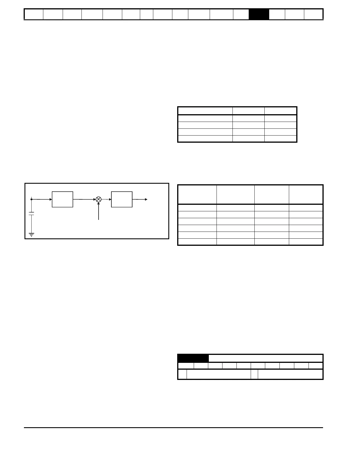
Line power supply loss and controlled standard ramp:
The DC bus voltage controller becomes active if line power supply
loss detection is enabled and the drive supply is lost or controlled
standard ramp is being used and the machine is regenerating. The
DC bus controller attempts to hold the DC bus voltage at a fixed
level by controlling the flow of current from the drive inverter into its
DC bus capacitors. The output of the DC bus controller is a current
demand which is fed into the current PI controller as shown in the
following diagram.
Although it is not usually necessary the DC bus voltage controller
can be adjusted with Pr 5.31. However, it may often be necessary to
adjust the current controller gains to obtain the required
performance. If the gains are not suitable it is best to set up the drive
in torque control first. Set the gains to a value that does not cause
instability around the point at which field weakening occurs. Then
revert back to open loop speed control in standard ramp mode. To
test the controller the supply should be removed while the motor is
running. It is likely that the gains can be increased further if required
because the DC bus voltage controller has a stabilising effect,
provided that the drive is not required to operate in torque control
mode.
Closed-loop vector and Servo
The Kp and Ki gains are used in the voltage based current controller.
The default values give satisfactory operation with most motors.
However it may be necessary to change the gains to improve the
performance. The proportional gain (Pr 4.13) is the most critical value in
controlling the performance. Either the value can be set by auto-tuning
(see Pr 5.12) or it can be set by the user so that
Pr 4.13 = Kp = (L / T) x (I
fs
/ V
fs
) x (256 / 5)
Where:
T is the sample time of the current controllers. The drive
compensates for any change of sample time, and so it should be
assumed that the sample time is equivalent to the lowest sample
rate of 167μs.
L is the motor inductance. For a servo motor this is half the phase to
phase inductance that is normally specified by the manufacturer. For
an induction motor this is the per phase transient inductance (σL
s
).
This is the inductance value stored in Pr 5.24 after the autotune test
is carried out. If σL
s
cannot be measured it can be calculated from
the steady state per-phase equivalent circuit of the motor as follows:
I
fs
is the peak full scale current feedback = K
C
x √2 / 0.45. Where K
C
is defined in Table 13-5.
V
fs
is the maximum DC Bus voltage.
Therefore:
Pr 4.13 = Kp = (L / 167μs) x (K
C
x √2 / 0.45 / V
fs
) x (256 / 5)
= K x L x K
C
Where:
K = [√2 / (0.45 x V
fs
x 167μs)] x (256 / 5)
This set-up will give a step response with minimum overshoot after a
step change of current reference. The approximate performance of the
current controllers will be as given below. The proportional gain can be
increased by a factor of 1.5 giving a similar increase in bandwidth,
however, this gives at step response with approximately 12.5%
overshoot.
The integral gain (Pr 4.14) is less critical and should be set so that
Pr 4.14 = Ki = Kp x 256 x T /
τ
m
Where:
τ
m
is the motor time constant (L / R).
R is the per phase stator resistance of the motor (i.e. half the
resistance measured between two phases).
Therefore
Pr 4.14 = Ki = (K x L x K
C
) x 256 x 167μs x R / L
= 0.0427 x K x R x K
C
The above equation gives a conservative value of integral gain. In some
applications where it is necessary for the reference frame used by the
drive to dynamically follow the flux very closely (i.e. high speed closed-
loop induction motor applications) the integral gain may need to have a
significantly higher value.
13.21.7 Start / stop logic modes
This parameter is provided to allow the user to select several predefined
digital input routing macros to control the sequencer. When a value
between 0 and 3 is selected the drive processor continuously updates
the destination parameters for digital I/O T25, T26 and T27, and the
enable sequencer latching bit (Pr 6.40). When a value of 4 is selected
the destination parameters for these digital I/O and Pr 6.40 can be
modified by the user.
DC Bus
voltage
controller
P Pr
4.13
I Pr
4.14
Frequency
reference
Active current
DC Bus
capacitor
Current
demand
Drive voltage rating Vfs K
200V 415V 2322
400V 830V 1161
575V 990V 973
690V 1190V 809
Switching
frequency
kHz
Current control
sample time
μs
Gain
bandwidth
Hz
Phase
delay
μs
3 167 TBA 1160
4 125 TBA 875
6 83 TBA 581
8 125 TBA 625
12 83 TBA 415
16 125 TBA 625
6.04 Start / stop logic select
RW Uni US
Ú
0 to 4
Ö
0
σL
s
L
s
L
m
2
L
r
----------
⎝⎠
⎜⎟
⎛⎞
–=
 Loading...


