124 Functional description CG Drives & Automation 01-7318-01r1
11.11.3 Udc controller parameters
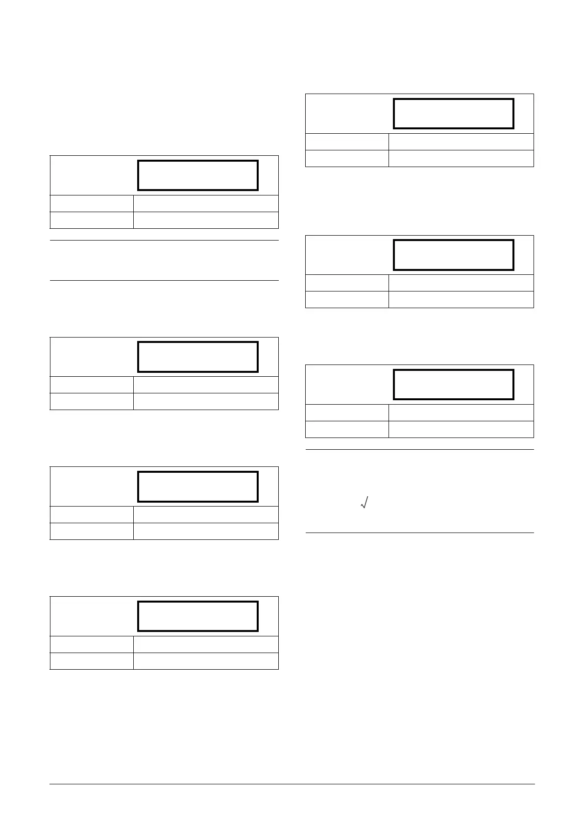
[O30]
Main menu for DC-link voltage (Udc) parameters.
Udc reference [O31]
DC-link voltage reference value.
Udc ramp time [O32]
Udc ramp time, defined as time from 0 ->1000V.
Udc PI Gain controller [O33]
Proportional gain of Udc PI controller.
Udc PI Time controller [O34]
Integral time constant of Udc PI controller.
Udc PI Max limit [O35]
Udc PI controller max limit, i.e. active power limit.
Udc PI Charge limit [O36]
Udc PI controller max charge limit during synchronization,
i.e. during Udc charging.
Udc margin [O37]
Udc reference control margin from actual output voltage.
Default: 1.05*Upeak
Range Upeak to Umax
NOTE:
Actual DC - link voltage reference value is limited via
actual supply voltage and [O37 Udc margin].
Default: 1s
Range 0.0 - 10.0s
Default: 5.0
Range 0.0 - 10.0
Default: 0.2s
Range 0.0 - 10.0s
O31 Udc ref
Stp 1.05*Upeak
Default: 200%
Range 0 - 400%
Default: 20%
Range 0 - 100%
Default: 5%
Range 0.0 - 20.0%
NOTE:
Actual internal DC - link voltage reference value is
limited via actual supply voltage and [O37 Udc margin],
i.e.
where Uac is the phase to phase RMS voltage.

 Loading...