46 FDUL/VFXR/FDUG/VFXG/AFR/AFG Main features CG Drives & Automation, 01-7318-01r1
7.17.3.1.3 Dynamic voltage support during
UVRT and OVRT
The AFG grid voltage FRT detection is always performed
based on the measured/estimated positive sequence (U+)
and the negative sequence (U-) voltage components.
Additionally, FRT detection is also performed on the
individual line-line or phase-neutral voltages.
The AFG behavior during UVRT and OVRT are defined by
the setup FRT mode via parameters [G325] for UVRT and
[G327] for OVRT. The supported FRT modes are:
I(cont) Continued operation mode where the pre-fault
P and Q control is maintained to the extent
possible.
I(Q) Additional dynamic reactive current injection
of both positive (I+) and negative (I-) sequence
components according to EN 50549-2 (2019,
section 4.7.4.2.1) with Q priority, i.e. the active
current is limited in favor for reactive current if
the AFG current limit is reached.
I(P) Additional dynamic reactive current injection
of both positive (I+) and negative (I-) sequence
components according to EN 50549-2 (2019,
section 4.7.4.2.1) with P priority, i.e. the
reactive current is limited if the AFG current
limit is reached.
I(zero) Zero current mode where the output current is
immediately reduced below 10% of the rated
AFG current as long as the grid voltage is
outside the static voltage range.
Note, that this mode corresponds to the
operation state "momentary cessation" as
defined in UL 1741 (Supplement SA) or
alternatively to an active "gate blocking"
operation state.
In order to avoid activation of the dynamic voltage support
for small voltage variations, a configurable voltage
insensitivity range (dead-band) can be defined via parameter
[G323].
Additionally, configurable voltage thresholds for automatic
activation of the zero current mode I(zero) for both OVRT
and UVRT can be defined respectively in parameters
[G326] and [G328].
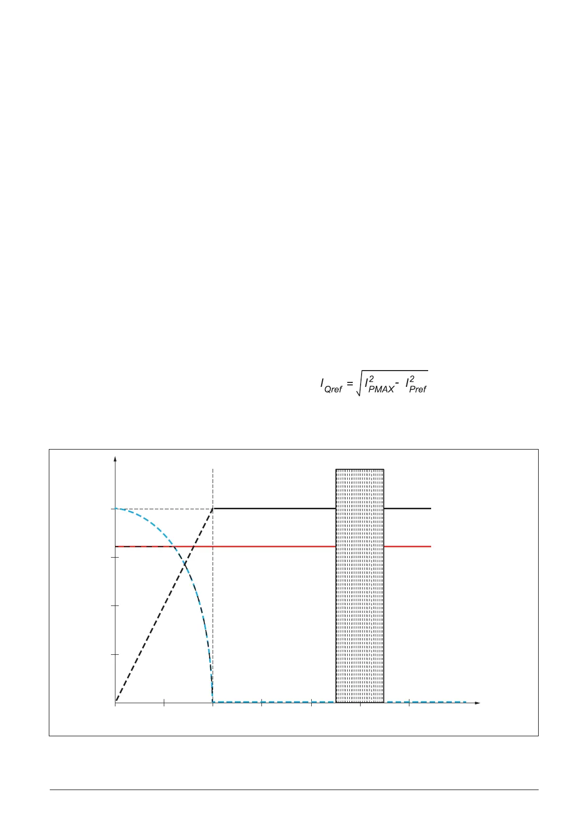
The active and reactive current limits during voltage fault
ride through (UVRT and OVRT) are individual and defined
via parameters [G321] and [G322], respectively. For stable
fault recovery, an additional active current limitation based
on the actual grid voltage during the fault is needed as
shown in Fig. 42. For a remaining grid voltage below 40%
the active current limit is linearly reduced to 0 and instead
shifted to a reactive current demand given in below equation
up to the reactive current limit.
Fig. 42 Active (I
P
) and reactive (I
Q
) current limiting during UVRT/OVRT
I [%]
I.Q(MAX)
I.Q(<40%)
I.P(<40%)
I.P(MAX)
U [%]
120100806040200
25
50
75
100

 Loading...