CG Drives & Automation, 01-7318-01r1 FDUL/VFXR/FDUG/VFXG/AFR/AFG Main features 47
The maximum time for dynamic grid support is defined in parameter [G324]. If the maximum time expires then the AFG unit
resumes operation according to the FRT mode I(cont), i.e. continued operation mode.
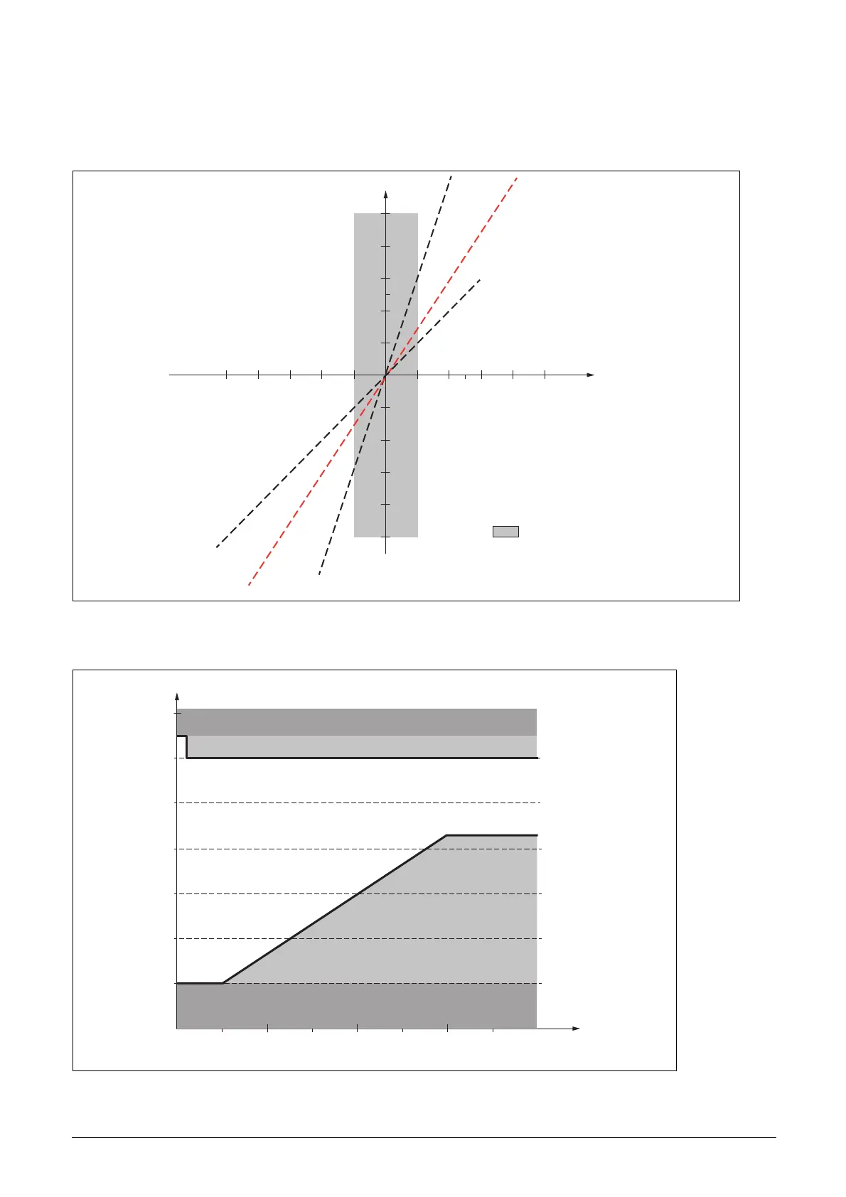
The additional reactive current injection for modes I(
Q
) and I(
P
) can be configured via individual gain parameters [G329] and
[G32A] for the positive- and negative sequence reactive current support as shown in Fig. 43.
Fig. 43 FRT modes I(Q) and I(P) dynamic reactive current support for positive- and negative sequence according to EN 50549-
2.Dedicated trip areas in the time-domain for both UVRT and OVRT are configurable via parameters [G32D]-[G32G] for
UVRT and [G32H]-[G32K] for OVRT as shown in Fig. 44 (Source IEC 50549-2).
Fig. 44 UVRT and OVRT trip area description
Gradient k=3
Gradient k=2
Gradient k=6
Approximated behaviour of
a synchronous generator
100%
100%
50%
20%
25%10%-10%-50%
20%
Δl / l
Qr
c
ΔU/ U
Limitation of the
voltage with
underexcited
operation
Support of the
voltage with
overexcited
operation
With
I
r
: Rated current
I
r
: Additional reactive current
Insensitivity range
U [%]
Time [s]
[t2=3s],
[U2=85%]
[t2=0.1s],
[U2=120%]
[t1=0.5s],
[U1=20%]
[t1=0.1s],
[U1=130%]
3210 1.50.5
80
60
40
20
100
120
140
OVRT trip area 1 defined above U1
OVRT trip area 2 defined right of line [t1,U1] -[t2,U2]
UVRT trip area 2
defined right of
line [t1,U1] -[t2,U2]
UVRT trip area 1 defined below U1

 Loading...