AcuLaser C2800/C2800D/C3800/C3800D Revision C
TROUBLESHOOTING Engine-related Trouble FIP 106
Confidential
FIP 1-27 Service Req E550 (Fan Motor Failure)
Possible parts that caused the error
Troubleshooting
FAN MAIN
FAN DUP
HARNESS ASSY LV TOP
LVPS
PWBA MCU
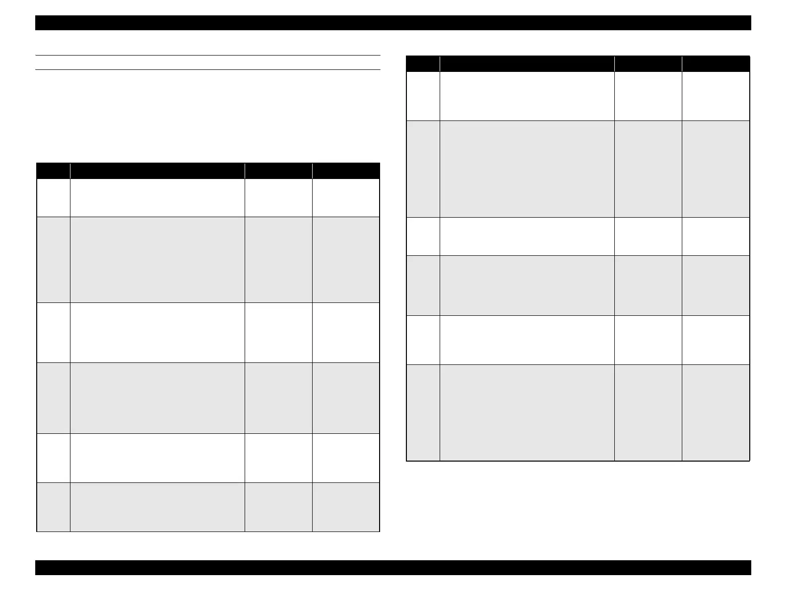
Step Check Yes No
1
Check after turning the power OFF and ON.
Does the error recur even when the power is
turned off and back on again?
Go to Step [2]. End of procedure
2
Check the connection of the FAN MAIN and
the FAN DUP
Check the connection state of the following
items.
FAN MAIN - LVPS
FAN DUP - PWBA DUP
Are P/J503 and P/J427 connected correctly?
Go to Step [3]. Reconnect FAN
MAIN (P/J503)
and FAN DUP (P/
J427) correctly.
3
Check the power voltage supply to FAN
DUP.
Measure the voltage between PWBA DUP
ground <=> P/J427-1PIN.
Is the power voltage (+24 V) output?
Replace the FAN
DUP. (p.349)
Go to Step [4].
4
Check the connection between PWBA DUP
and PWBA MCU
Check the connection state between PWBA
DUP and PWBA MCU.
Are P/J428, P/J2720, P/J272, and P/J27
connected correctly?
Go to Step [5]. Reconnect the
P/J428, P/J2720,
P/J272, and P/J27
correctly.
5
Check the continuity of the HARNESS ASSY
DUP UNIT
Is there normal continuity between P/J428 and
P/J2720?
Go to Step [6]. Replace the
HARNESS
ASSY DUP
UNIT.
6
Check the continuity of the HARNESS ASSY
FRONT COVER
Is there normal continuity between P/J2720 and
P/J272?
Go to Step [7]. Replace the
HARNESS
ASSY FRONT
COVER.
Step Check Yes No
7
Check the continuity of the HARNESS ASSY
R SIDE
Is the continuity between P/J27 <=> P/J2720
normal?
Go to Step [6]. Replace the
HARNESS
ASSY R SIDE.
8
Check the power voltage supply to PWBA
DUP
1. Close the interlock switch (HARNESS
ASSY INTERLOCK) before performing
the following work.
2. Measure the voltage between PWBA
MCU ground <=> P/J27-A17, A18PIN.
Is the power voltage (approx. +24 V) output?
Go to Step [9]. Replace the
PWBA MCU.
(p.343)
9
Replace of the PWBA DUP
Replace the PWBA DUP. (p.349)
Was the trouble fixed?
End of procedure Go to Step [10].
10
Check the power voltage supply to FAN
MAIN
Measure the voltage between LVPS ground <=>
P503-1PIN.
Is the power voltage (+24 V) output?
Replace the FAN
MAIN. (p.327)
Go to Step [11].
11
Check the continuity of the HARNESS ASSY
LV TOP
Is the continuity between P/J14 <=> P/J501
normal
?
Go to Step [12]. Replace the
HARNESS
ASSY LV TOP.
12
Check the power voltage output from the
LVPS.
1. Measure the voltage between LVPS
ground <=> P503-1PIN.
2. Close the interlock switch (HARNESS
ASSY INTERLOCK) before performing
the following work.
Is the power voltage (approx. +24 V) output?
Replace the
PWBA MCU.
(p.343)
Replace the
LVPS. (p.327)